Summary and Next Steps
A recap of designing robot parts in BetterCad with the catalogue, pockets, mounts and gears, and where to go next
By Kevin McAleer, 5 Minutes
Page last updated November 21, 2026

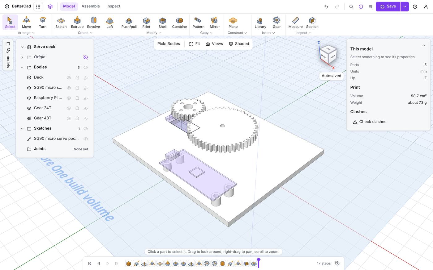
You started with a bare plate and a bag of bought parts. You finish with a printed deck that holds a servo and a microcontroller and drives a gear train, and you looked up almost no dimensions to get there.
What you learned
| Lesson | The idea to keep |
|---|---|
| Reference bodies | Bought parts live in the model to design around, and never print |
| The catalogue | Servos, motors, boards, sensors and bearings are one click away |
| Measure before you trust | Checked parts follow a drawing. The rest need callipers |
| Cutting a pocket | One command makes a sketch, a cut at a sliding fit, and the screw holes |
| Standoffs | Pick a board’s pattern and its screw comes with it |
| Horn mounts | Bolt to the horn. Never print splines |
| Your first gear | Module is the tooth size, and pitch diameter is module times teeth |
| Bores and small gears | D-flat for motors, horn bore for servos, profile shift under 17 teeth |
| Meshing gears | A mating gear sits at the right distance and follows its partner |
| Racks, pulleys and belts | Racks slide, belts reach, and stock belts set the spacing |
| Mesh to editable | Recognise features turns an STL’s holes into steps you can change |
A checklist for any robot part
Before you press print on a part that holds something:
- Is every bought part in the model as a reference?
- Did you measure the ones the catalogue hasn’t checked?
- Are pockets cut with a fit, and holes made with the Hole tool, so your printer’s calibration applies?
- Do gears that mesh share a module, and has the small one got 17 teeth or a profile shift?
- With the references hidden, is what’s left exactly what you mean to print?
Quick reference
| To do this | Use |
|---|---|
| Bring in a part you own | Insert, Import as a reference |
| Place a catalogue part | Insert, Catalogue. T turns it |
| Cut its pocket | Right-click the part, Cut pocket |
| Add standoffs or a horn mount | Insert, Mount |
| Make a gear, rack or pulley | Gear, then choose the Form |
| Add a meshed partner | Right-click a gear, Add mating gear or Add rack |
| Mesh two existing gears | Select both, Ctrl+K, Mesh gears |
| Fit a belt | Select two pulleys, right-click, Fit a belt |
| Change a gear later | Right-click its step on the timeline, Edit gear |
| Make an STL’s holes editable | Right-click it, Recognise features |
What’s Next
Your deck’s gears mesh on screen, but they don’t turn yet. BetterCad can do that too. The Assemble tab has joints, poses, a clash check that sweeps every joint through its range, and a URDF export for simulators.
- Make It Move with BetterCad is the next course. It builds a two-joint arm, and one lesson comes back to this deck to make its gears drive each other
Also worth a look:
- Learn BetterCad if you skipped the basics
- Print It Right with BetterCad to calibrate the fits and holes this course relies on
- Wire It Up - Electronics in Snakie to wire the servo and Pico you’ve just mounted
- Getting Started with Snakie to write the MicroPython that sweeps the servo
And for build videos, robot projects and livestreams, subscribe to Kevin McAleer on YouTube.
Try it Yourself
- Design a mount for a part that isn’t in the catalogue. Find or measure its size, model it roughly from Library shapes, make it a reference, and build round it.
- Design a two-stage gearbox: two 3 : 1 pairs for 9 : 1 overall. How small can you make it?
- Design a gripper: one servo, a gear, and two racks that move in opposite directions.
Check your understanding
Quick quiz 1 of 3
Which two things let your printer’s calibration apply to a mount automatically?
Quick quiz 2 of 3
What is the safest way to attach a printed part to a servo?
Quick quiz 3 of 3
What do two gears need in common to mesh?
You can use the arrows ← → on your keyboard to navigate between lessons.
Comments