Standoffs for a Board
Add standoffs for a Raspberry Pi Pico or Pi with the BetterCad Mount tool, using built-in hole patterns and screw or heat-set insert holes
By Kevin McAleer, 6 Minutes
Page last updated November 21, 2026

A circuit board shouldn’t sit flat on a printed plate. Its solder joints need air under them, and it needs something to screw into. The answer is a standoff: a short post with a hole down the middle.
A Pico needs four, 47 mm apart one way and 11.4 mm the other. You don’t need to remember that. The Mount tool knows.
Start the Mount tool
- Click the word Insert and choose Mount.
The bar says “Click a flat face where the mount goes.”
- Click the top of the deck, in the open area in front of the servo.
One standoff appears where you clicked, and the Mount panel opens.
| Setting | What it does |
|---|---|
| Kind | Standoffs, or a Horn mount (next lesson) |
| Screw | The screw the holes are sized for |
| Layout | One standoff, a pattern, or the points you click |
| Hole | Through, or Insert |
| Height and Width | The size of each post |
| Standoff X and Y | Where the last one is, from the face’s centre |
You can keep clicking to add more posts one at a time, and Remove last takes the newest one away. For a board there’s a faster way.
Pick a pattern
- Open the Layout menu.
It lists three general patterns and one for every catalogue part that has screw holes:
- One standoff
- Rectangle, 40 × 30 mm
- Circle of 4, 30 mm
- SG90 and MG90S micro servo (27.8 mm), MG996R servo (49.5 × 10 mm)
- Raspberry Pi Pico and Pico W (47 × 11.4 mm)
- Raspberry Pi Zero 2 W (58 × 23 mm)
- Raspberry Pi 4 Model B and Raspberry Pi 5 (58 × 49 mm)
- Choose Raspberry Pi Pico (47 × 11.4 mm).
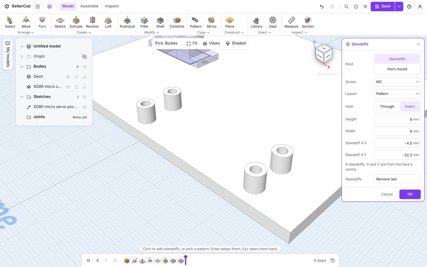
Four posts replace the one, centred where it was. Notice Screw changed to M2 by itself: picking a part’s pattern also picks its screw.
Through or Insert
Hole decides what’s inside each post.
- Through makes a printed clearance hole all the way down, through the post and the plate. A screw goes in from one side and a nut holds it on the other.
- Insert makes a hole at the top sized for a heat-set insert: a small brass thread you press in with a soldering iron. The board then screws down from above, and you can take it off and put it back as often as you like.
Inserts are the neater choice for anything you’ll service. Through holes need no extra parts. Pick Insert for the project if you have M2 inserts, Through if you don’t.
Size and place
- Height is how far the board sits off the plate. The default 6 mm leaves room for solder joints underneath. Use more if your board has header pins pointing down.
- Width is the post’s diameter. 6 mm is solid enough for M2 and M2.5.
For the project, the pattern should be centred 20 mm to the right of the middle and 38 mm towards the front. Click the deck near there. If you want it exact, the posts’ positions are stored in the step and you can retype Standoff X and Y, but placing by eye is fine here: the board only has to miss the gears.
A word on those X and Y numbers. They’re measured from the centre of the face you clicked. On a plain plate that’s the middle. On a face with a pocket cut out of one end the centre shifts slightly towards the other end, because it’s the middle of what’s left. If a mount has to be exact, add it before you cut pockets in the same face.
- Click OK, or press Enter.
The posts are joined to the deck, and one Standoffs step sits on the timeline. Right-click it and choose Edit to change anything later.
Check it with the real board
Drop the board on to see it fit.
- Open Catalogue from the Insert menu and click Raspberry Pi Pico.
- Click the deck near the standoffs.
- In Properties, set the Pico’s Position so it’s centred over the pattern, and set Z to
10: the 4 mm deck plus 6 mm of standoff.
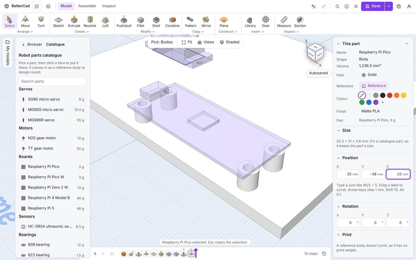
The Pico’s four corner holes line up with the four posts. It’s a reference body, so it’s only there for you to look at.
Try it Yourself
- On a new 100 × 70 × 3 mm box, add standoffs with the Raspberry Pi Zero 2 W pattern. Which screw does it choose?
- Edit the step and change Height to 10. Do all four posts change?
- Add a second Mount step using Circle of 4, 30 mm. What might that suit?
Common Issues
Problem: I clicked and nothing happened. Solution: Click a flat face of a printed body. The tool doesn’t place mounts on the ground. Why: A standoff has to be joined to something.
Problem: The pattern landed half off the plate. Solution: Click nearer the middle of the space you have, or retype the X and Y. Why: A pattern is centred on the point you clicked.
Problem: My heat-set inserts are loose in the printed holes. Solution: Measure your inserts and print a single test post before the whole plate. Sizes vary between makers. Why: The Insert hole is sized for a typical insert of that thread.
Check your understanding
Quick quiz 1 of 3
What happens to the Screw setting when you pick the Raspberry Pi Pico pattern?
Quick quiz 2 of 3
What is the Insert hole option for?
Quick quiz 3 of 3
Where are Standoff X and Y measured from?
You can use the arrows ← → on your keyboard to navigate between lessons.
Comments