Project - A Geared Servo Deck
Build a 3D printable deck in BetterCad that holds an SG90 servo and a Raspberry Pi Pico and drives a 2 to 1 gear pair
By Kevin McAleer, 8 Minutes
Page last updated November 21, 2026

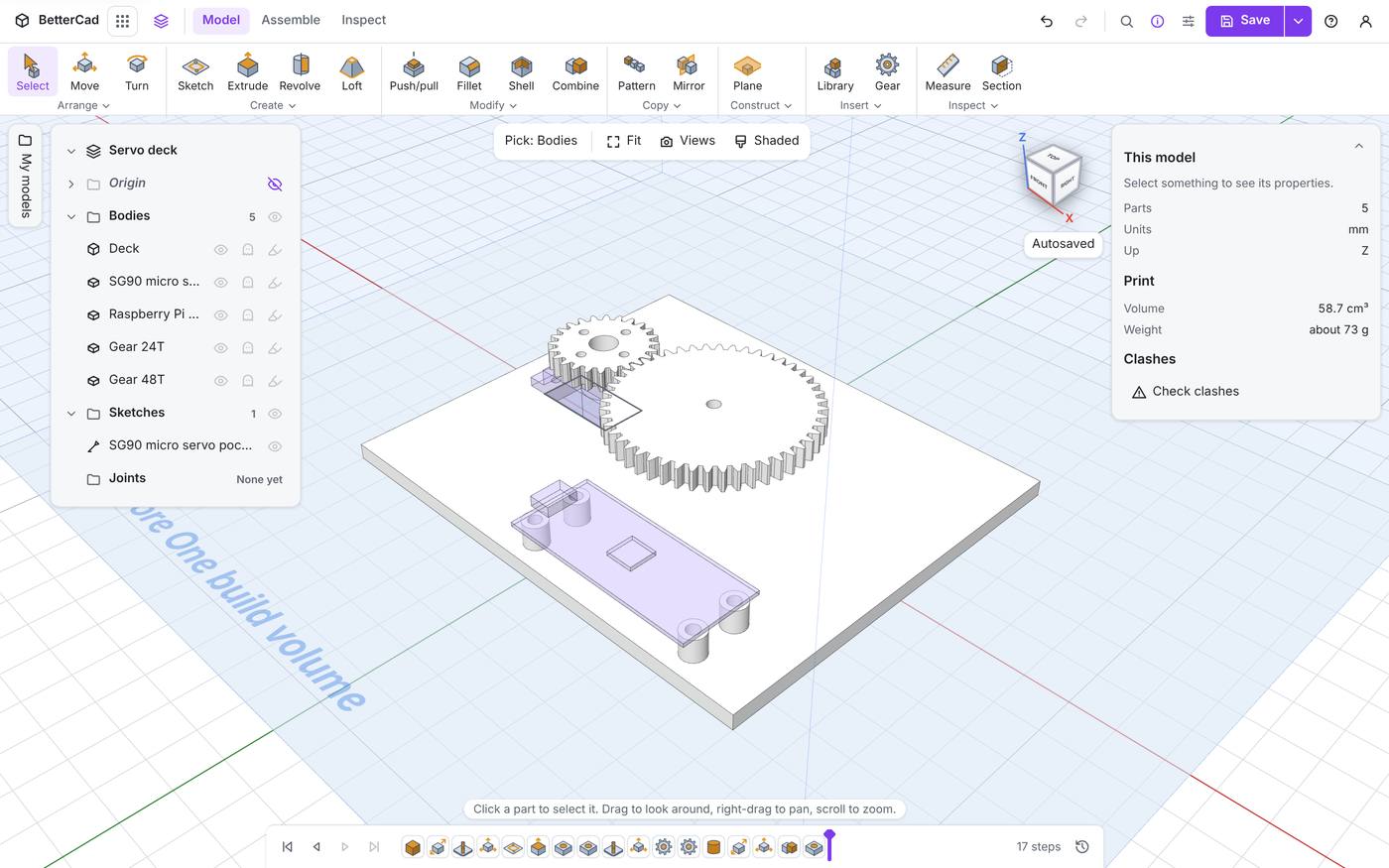
Time to put the whole course on one plate. You’ll build a deck that could be the top of a small robot: a micro servo dropped into a pocket, a Pico on standoffs, and a pair of gears that halve the servo’s speed and double its strength. Put a sensor or a head on the big gear and you have a pan mount with finer, stronger movement than the bare servo gives.
If you followed lessons 2, 4 and 5 in one model, you’ve done the first half already. Skip to step 4.
The plan
| Part | What it is | Printed? |
|---|---|---|
| Deck | A 120 × 100 × 4 mm plate with a servo pocket, four standoffs and a gear post | Yes |
| Drive gear | 24 teeth, module 1, bolted to the servo’s horn | Yes |
| Output gear | 48 teeth, turning on an M3 screw through the post | Yes |
| SG90 servo | From the catalogue | No, reference |
| Raspberry Pi Pico | From the catalogue | No, reference |
The numbers that tie it together:
module = 1
drive_teeth = 24
output_teeth = 48

ratio = output_teeth / drive_teeth                         # 2 : 1
centre_distance = module * (drive_teeth + output_teeth) / 2   # 36 mm

servo_shaft_x = -30
post_x = servo_shaft_x + centre_distance                   # 6 mm
So the servo’s shaft goes at X = -30 and the post for the big gear at X = 6.
Step 1: the deck and the servo
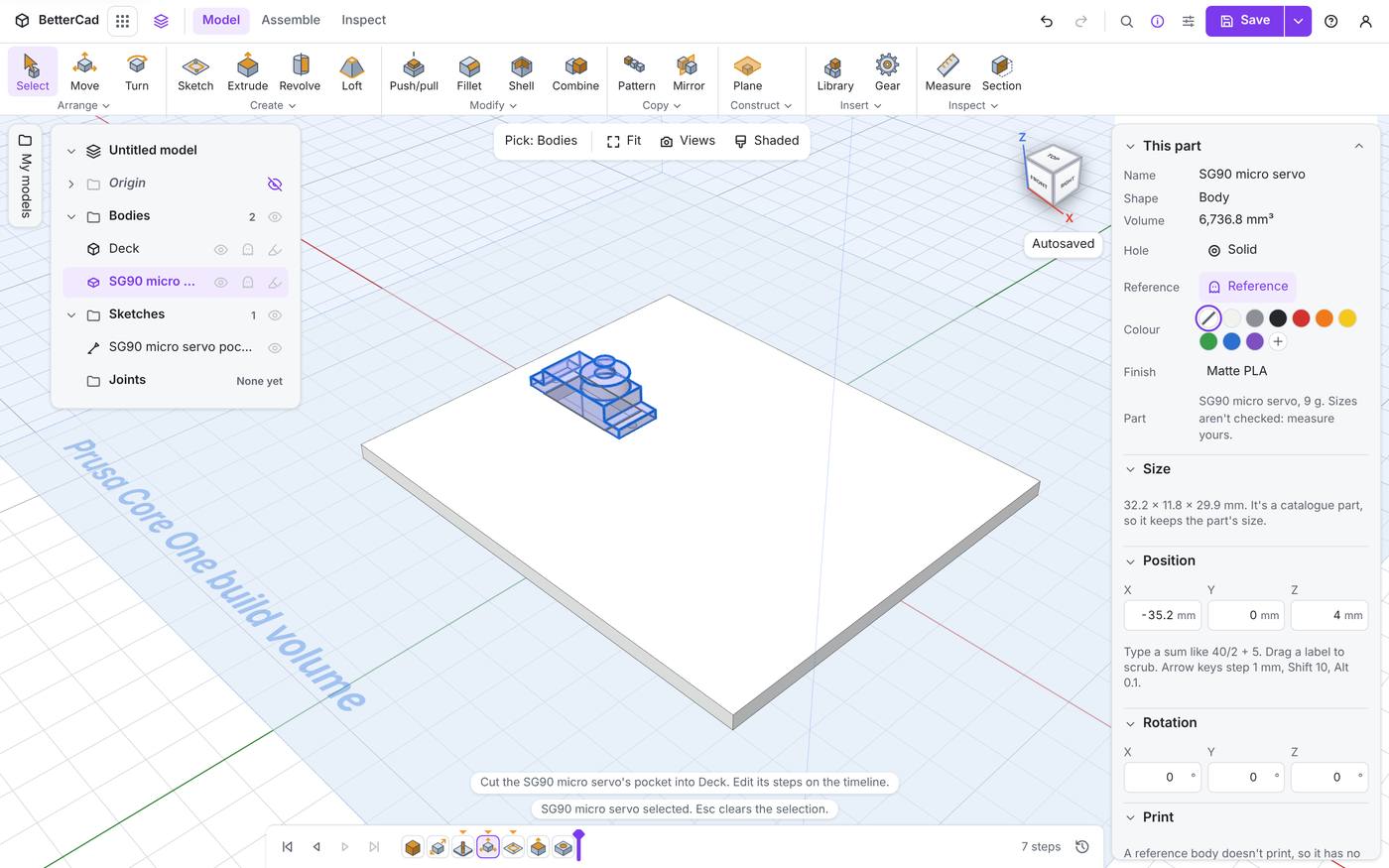
- Start a new model. Add a Box, size
120,100,4, and rename itDeck. - Insert, Catalogue, SG90 micro servo. Click the top of the deck towards the left.
- In Properties set the servo’s Position to X
-35.2, Y0, Z4.
The shaft is 5.2 mm off the servo’s centre, so it’s now at X = -30.
Step 2: the pocket
- Right-click the servo in the Browser and choose Cut pocket.
Step 3: the Pico
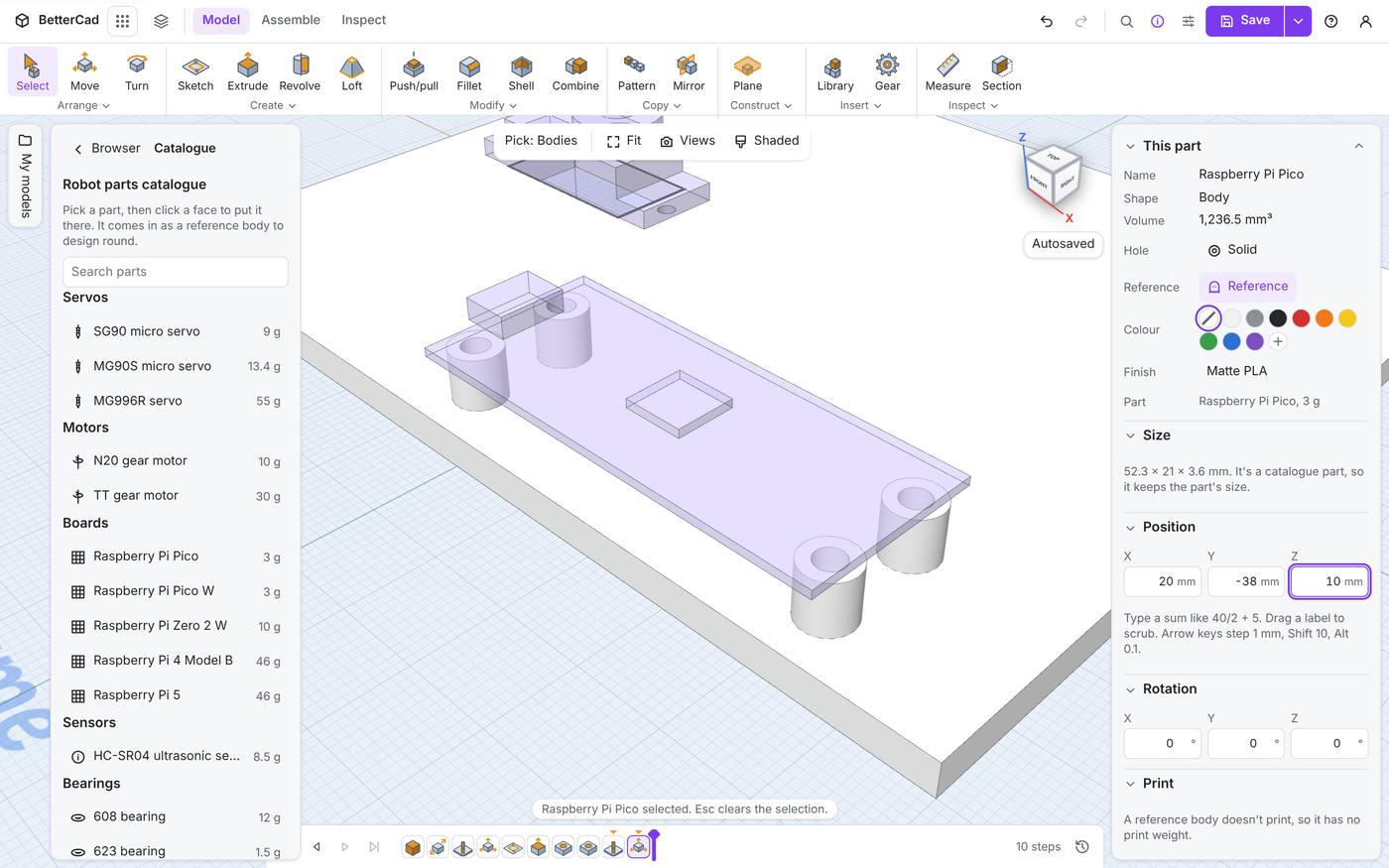
- Insert, Mount. Click the deck in the open space at the front right.
- Set Layout to Raspberry Pi Pico (47 × 11.4 mm).
- Choose Insert or Through for the holes, then click OK.
- From the Catalogue, place a Raspberry Pi Pico on the deck, move it over the standoffs and set its Z to
10.
Step 4: the drive gear
- Turn the view so you can see the top of the servo’s shaft.
- Click Gear, then click the round end of the shaft.
The gear stands on the shaft, centred on it.
- Set Teeth to
24and press Tab. - Set Bore to Servo horn.
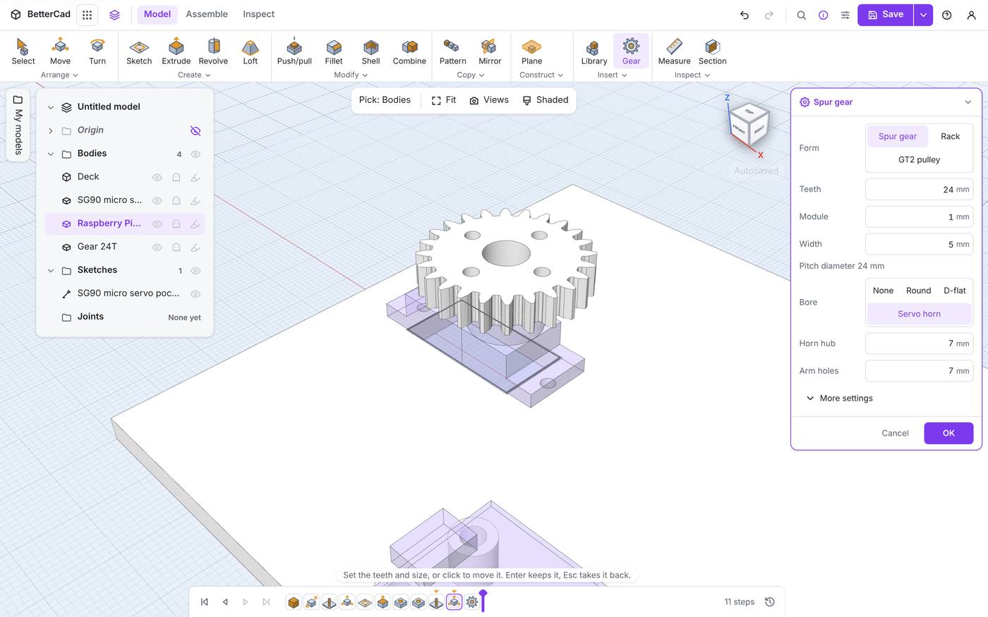
- Click OK.
Step 5: the output gear
- Right-click Gear 24T in the Browser and choose Add mating gear.
- Set Teeth to
48. - Leave Angle at
0so it sits along X. - It copied the horn bore, which is wrong for this gear. Set Bore to Round and type
3.4, a clearance hole for an M3 screw.
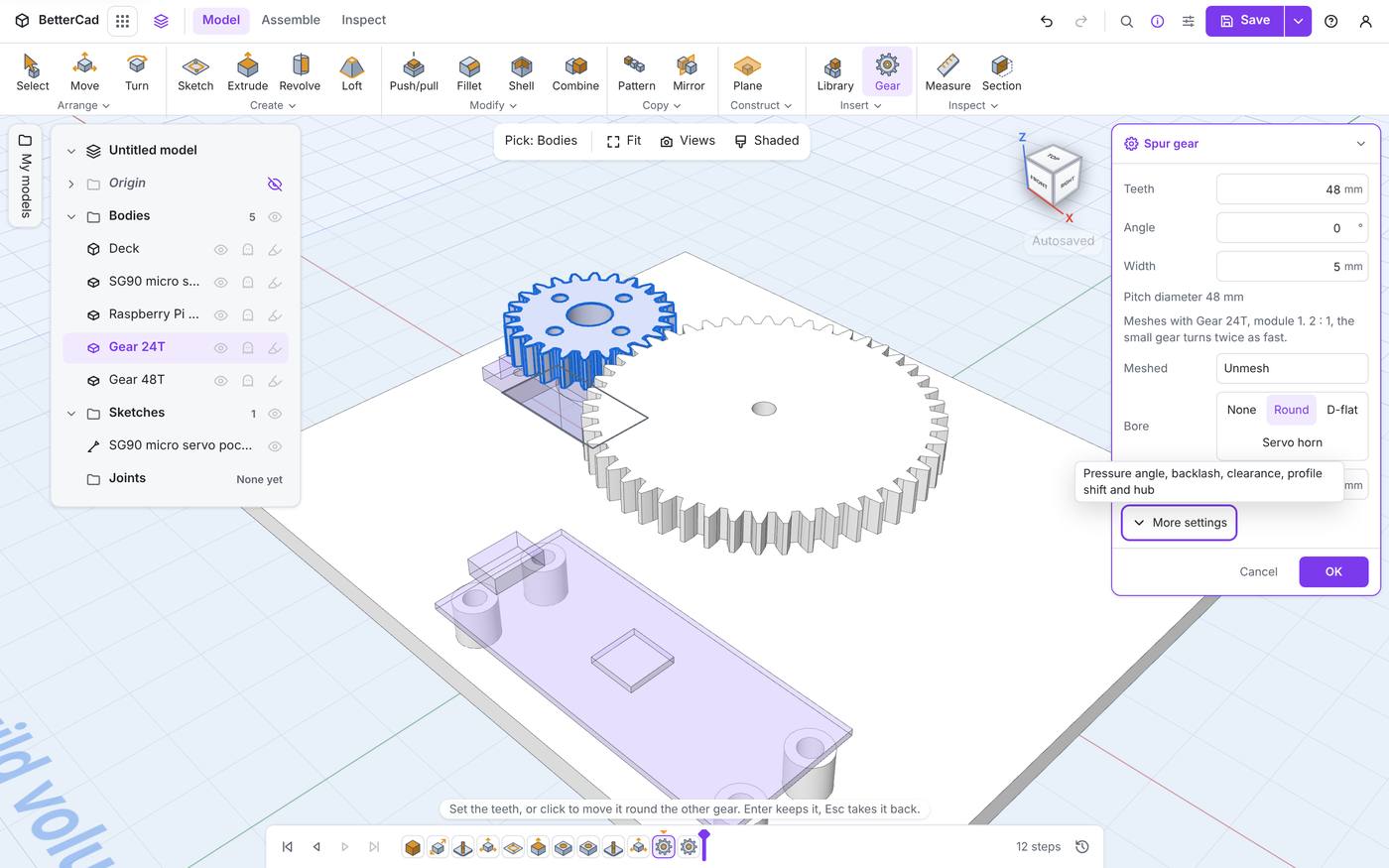
The panel confirms it: “Meshes with Gear 24T, module 1. 2 : 1, the small gear turns twice as fast.”
- Click OK.
Step 6: the gear post
The big gear is floating 14 mm above the deck. It needs something to stand on.
- Open the Library and click Cylinder.
- Set its size to
8,8,14. - Set its Position to X
6, Y0, Z4. - Rename it
Gear post.
Hide the big gear (Shift+H) to check the post is where the gear’s bore was.
The post is a separate body. Join it to the deck so they print as one piece:
- Click Deck in the Browser, then Ctrl-click Gear post.
- Press Ctrl+G to group them.
Now the axle hole:
- Press H for the Hole tool and click the top of the post.
- Leave Size at M3, set Hole X and Hole Y to
0, and keep Through all ticked.
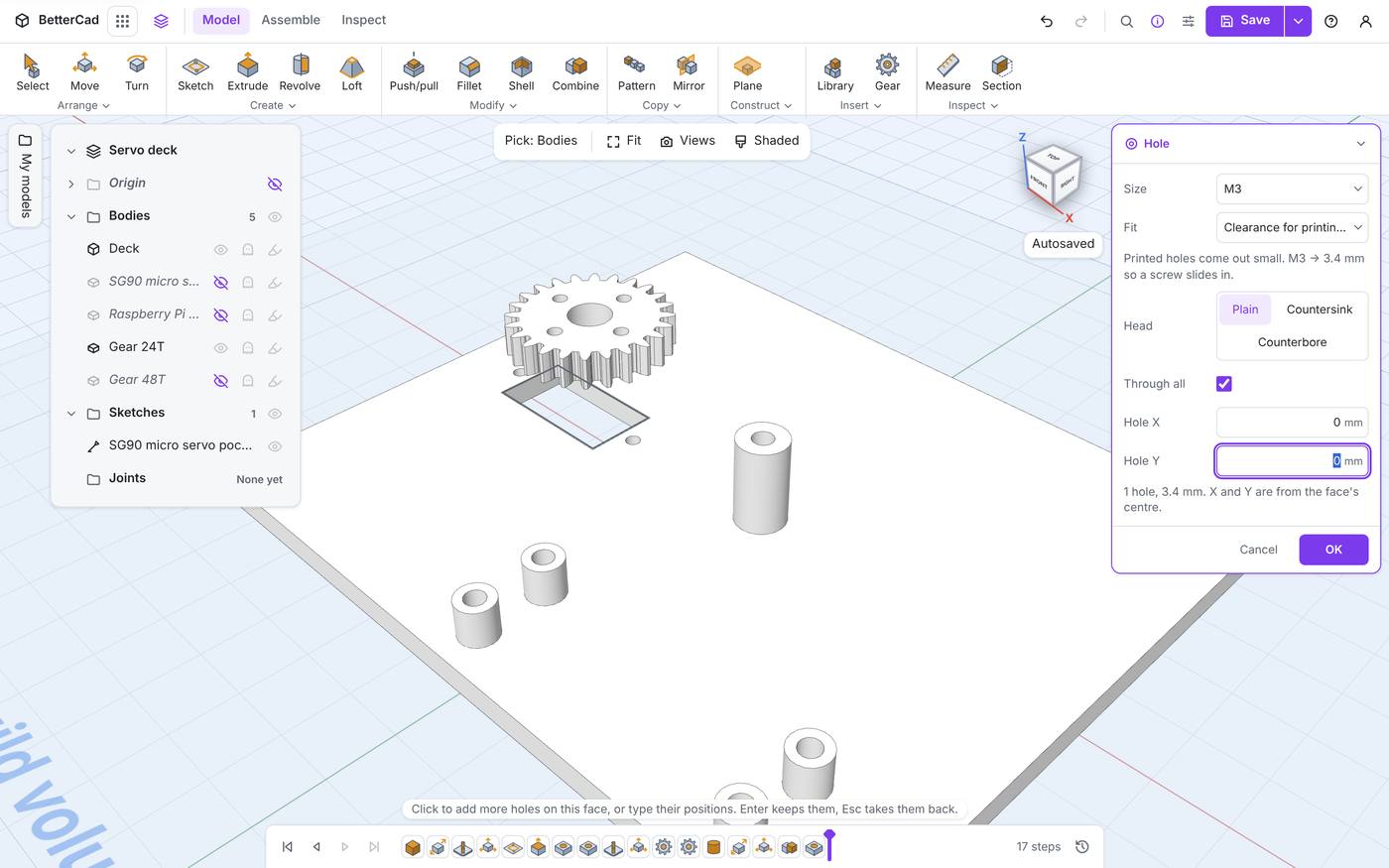
- Click OK.
The hole runs down through the post and out of the bottom of the deck. An M3 screw goes up from underneath, through the post and the gear, and a locking nut on top holds the gear on while leaving it free to turn.
- Right-click the hidden gear in the Browser and choose Unhide all.
Step 7: check it
Look down from the top with the view cube.
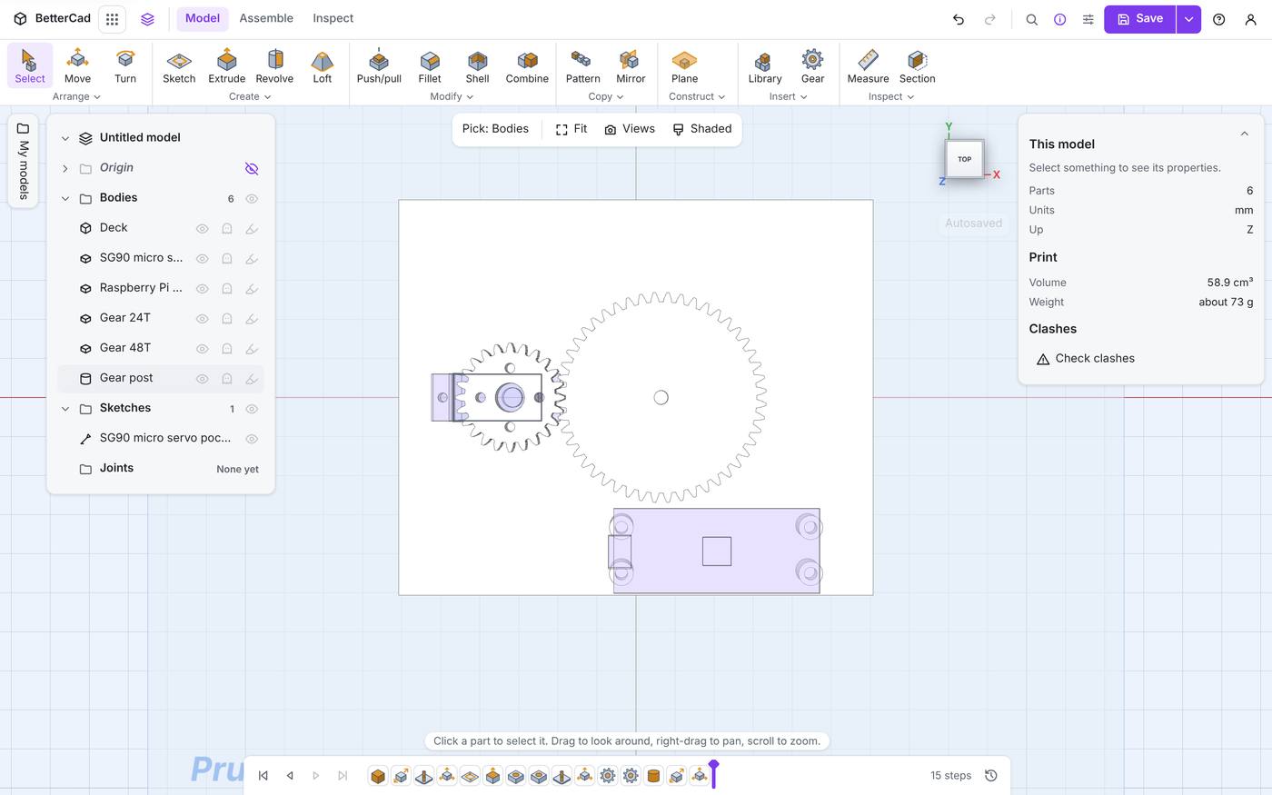
- The two gears’ teeth interlock at one point, and touch nowhere else.
- The big gear clears the Pico and the edge of the deck.
- The servo’s tabs sit over the two small screw holes.
With nothing selected, click Check clashes in Properties. It lists any bodies that overlap. Reference bodies are left out unless you tick Reference bodies.
Now hide the two references to see exactly what you’ll print.
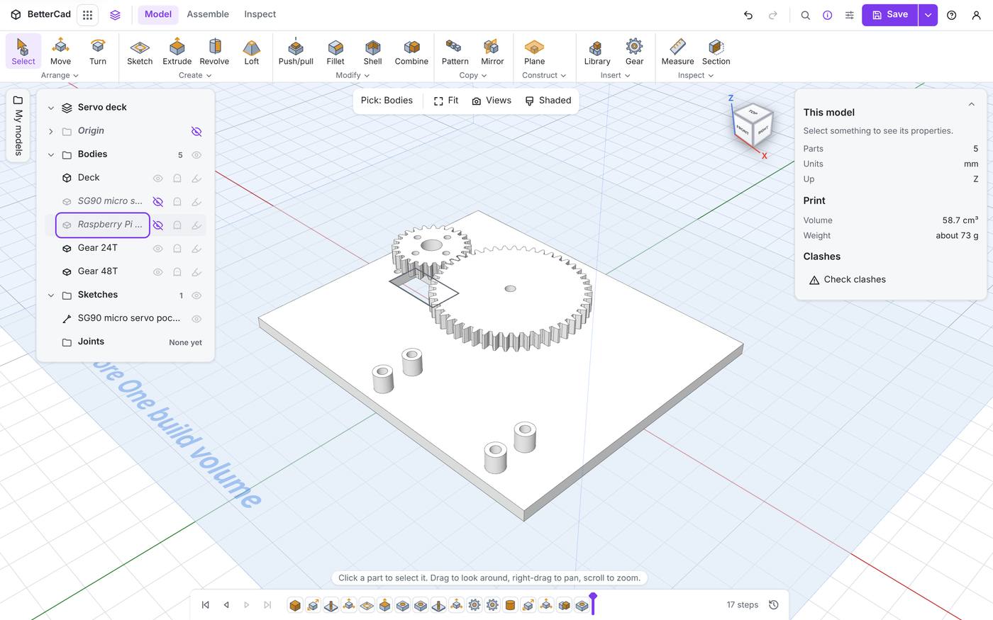
Properties puts the three printed parts at about 73 g of PLA at 15% infill.
Step 8: export
- Press Ctrl+E.
- Choose 3MF and Each on its own.
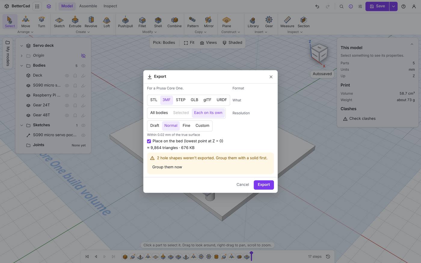
You’ll see the warning from lesson 1 about two hole shapes. Those are the servo and the Pico being left out, which is what you want. Don’t click Group them now.
- Click Export.
You get the deck and the two gears as separate files, ready for your slicer. Print the gears flat. Print the deck the way it’s drawn, standoffs up.
Put it together
- Push a cross-shaped horn onto the servo and bolt the 24-tooth gear to it with M2 screws.
- Drop the servo into its pocket and fix it with two M2 screws.
- Feed an M3 screw up through the deck and the post, drop the big gear on, and add a locking nut. Leave it just loose enough to spin.
- Screw the Pico to its standoffs.
Compare yours with the finished file: servo-deck.bcad.
Try it Yourself
- Edit Gear 24T and change it to 16 teeth. Does the 48-tooth gear follow? What’s the new ratio, and is the post still in the right place?
- Change the pattern to a Raspberry Pi Zero 2 W. Does it still fit on the deck?
- Add a horn mount or four screw holes to the top of the big gear so a sensor bracket can bolt on.
- Make the deck’s width and depth parameters, as you did for the phone stand in Learn BetterCad.
Common Issues
Problem: The gear landed on the servo’s body, not its shaft. Solution: Undo, zoom in on the shaft and click its round end face. Why: The gear stands on whichever flat face you click. The shaft’s end is a small target.
Problem: The post isn’t under the big gear. Solution: Check the servo’s X is -35.2 and the mating gear’s Angle is 0. Then the post belongs at X = 6. Why: The post’s place is the shaft’s X plus the 36 mm centre distance.
Problem: The gears mesh on screen but bind when printed. Solution: Edit both gears and raise Backlash under More settings by 0.05 mm, and check the big gear’s nut isn’t done up tight. Why: Printed teeth come out slightly fat, and a clamped gear can’t turn.
Problem: Ctrl+G grouped the wrong things. Solution: Undo. Select only Deck and Gear post before grouping. Why: Group joins every selected solid into one body.
Check your understanding
Quick quiz 1 of 3
Why does the gear post go at X = 6?
Quick quiz 2 of 3
The servo sweeps 180°. How far does the 48-tooth gear turn?
Quick quiz 3 of 3
Which parts end up in the exported files?
You can use the arrows ← → on your keyboard to navigate between lessons.
Comments