Design Robot Parts with BetterCad
Design 3D printed robot parts around real servos, boards and gears using the BetterCad catalogue, mounts and gear tools
By Kevin McAleer, 5 Minutes
Page last updated November 21, 2026

Overview
A robot is mostly other people’s parts. A servo from one shop, a Raspberry Pi Pico from another, a couple of bearings from a drawer. The parts you design and print are the bits in between: the deck the servo drops into, the posts the board screws to, the gear that turns the head.
That makes robot CAD a slightly different job from drawing a phone stand. You’re designing around things, and every one of them has to fit.
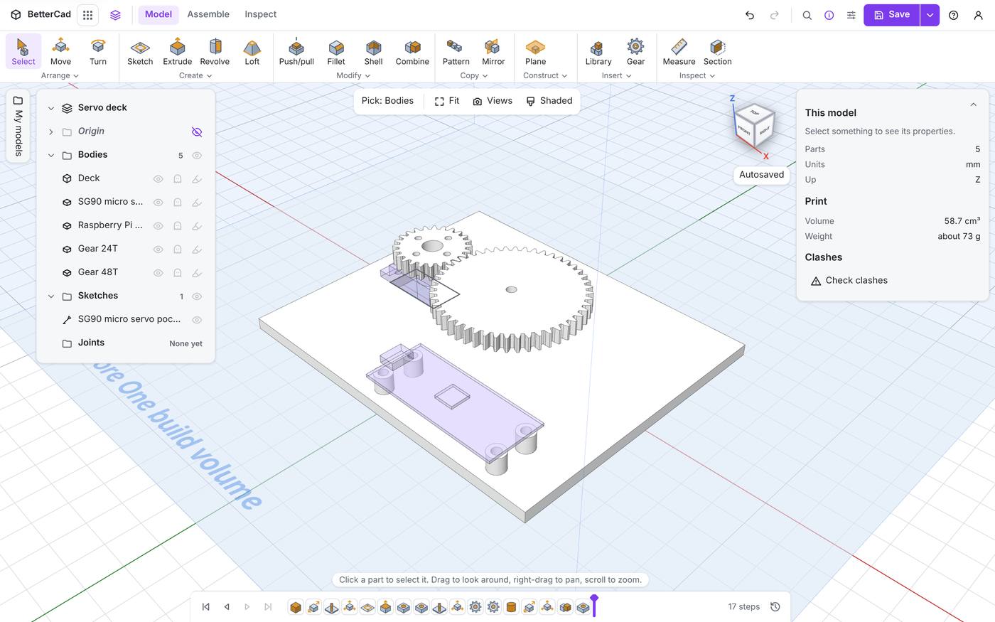
BetterCad has a set of tools built for exactly this. There’s a catalogue of common robot parts you can drop into a model, a one-click pocket cutter, a Mount tool for standoffs and servo horns, and a gear generator that makes gears, racks and belt pulleys that really mesh. This course works through all of them, then uses them together to build a geared servo deck: a plate that holds an SG90 servo and a Pico, with a 2 : 1 gear pair on top.
Course Content
- Reference bodies: parts you design around but never print
- The robot parts catalogue, and placing a servo on a plate
- Measuring a part before you trust its numbers
- Cutting a servo’s pocket and screw holes in one click
- Standoffs for a Pico or a Raspberry Pi, with screw or heat-set insert holes
- Horn mounts that bolt a servo horn to a printed part
- Spur gears: teeth, module, width and bore
- Small gears, undercut and profile shift
- Meshing two gears and reading the ratio
- Racks, GT2 pulleys and fitting a belt
- Turning an STL you downloaded into a part you can edit
- Project: a geared servo deck
Key Results
After this course you will be able to:
- Drop a servo, motor, board, sensor or bearing into a model and design round it
- Cut a pocket that the real part slides into
- Add a hole pattern for a Pico or a Pi without looking up a single dimension
- Generate a pair of gears with the ratio you want, at the right distance apart
- Choose a gear bore for a motor shaft or a servo horn
- Make the holes in a downloaded STL editable
What you’ll need
- A computer with a recent browser and a mouse
- BetterCad. It’s free and needs no account
- The basics from Learn BetterCad: adding shapes, Properties, the Browser and the timeline
- Your printer set up as in Print It Right with BetterCad, with its fits calibrated if you plan to print
To build the project for real you’ll also want an SG90 micro servo with its horns and screws, a Raspberry Pi Pico, a few M2 screws, one M3 screw about 20 mm long, and a set of callipers. None of that is needed to follow along on screen.
How the course works
Each lesson covers one tool with a small example. Steps to follow are numbered, keys look like T, and names of buttons and panels are in bold.
Most of the tools in this course live in the Insert group on the Model tab. Click the word Insert under the Library and Gear buttons and a menu opens with Catalogue, Gear, Mount and the import commands.
The course’s two files are here if you want them:
- bracket.stl, a small bracket to import in lessons 1 and 11
- servo-deck.bcad, the finished project. Drag it onto BetterCad to open it
BetterCad is in alpha and changes quickly. If a button has moved since these screenshots were taken, press Ctrl+K and type its name.
Try it Yourself
- Open BetterCad and click the word Insert on the Model tab. Read down the menu.
- Choose Catalogue and count the parts. Which one would you reach for first?
Check your understanding
Quick quiz 1 of 3
What makes robot CAD different from drawing a standalone part?
Quick quiz 2 of 3
Where are the Catalogue, Gear and Mount tools?
Quick quiz 3 of 3
What will the course project be?
You can use the arrows ← → on your keyboard to navigate between lessons.
Comments