From Mesh to Editable Part
Make the holes in a downloaded STL editable with BetterCad's Recognise features, then change them like any other step
By Kevin McAleer, 5 Minutes
Page last updated November 21, 2026

You found the perfect sensor bracket online. It’s an STL, and its holes are for M4 bolts. You only have M3.
In most CAD tools that’s the end of the road. An STL is a skin of triangles. A “hole” in it is a ring of little flat strips with no idea it’s a hole, so there’s nothing to resize. BetterCad’s Recognise features reads the triangles, works out what they used to be, and gives you a copy you can edit.
Recognise the holes
- Start a new model and import bracket.stl, the file from lesson 1. Either kind of import will do.
- In the Browser, right-click the bracket and choose Recognise features….
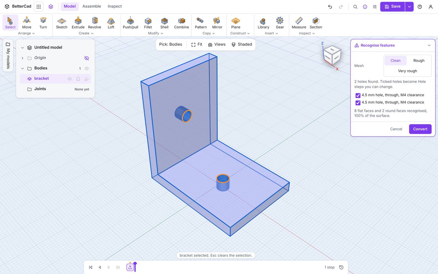
The panel reports what it found:
- “2 holes found. Ticked holes become Hole steps you can change.”
- Each hole with its size and a best guess at what it’s for: 4.5 mm hole, through, M4 clearance
- A summary: “8 flat faces and 2 round faces recognised, 100% of the surface.”
The holes’ rims are outlined on the model. Untick any hole you’d like left as it is, or click its rim in the view.
- Click Convert.
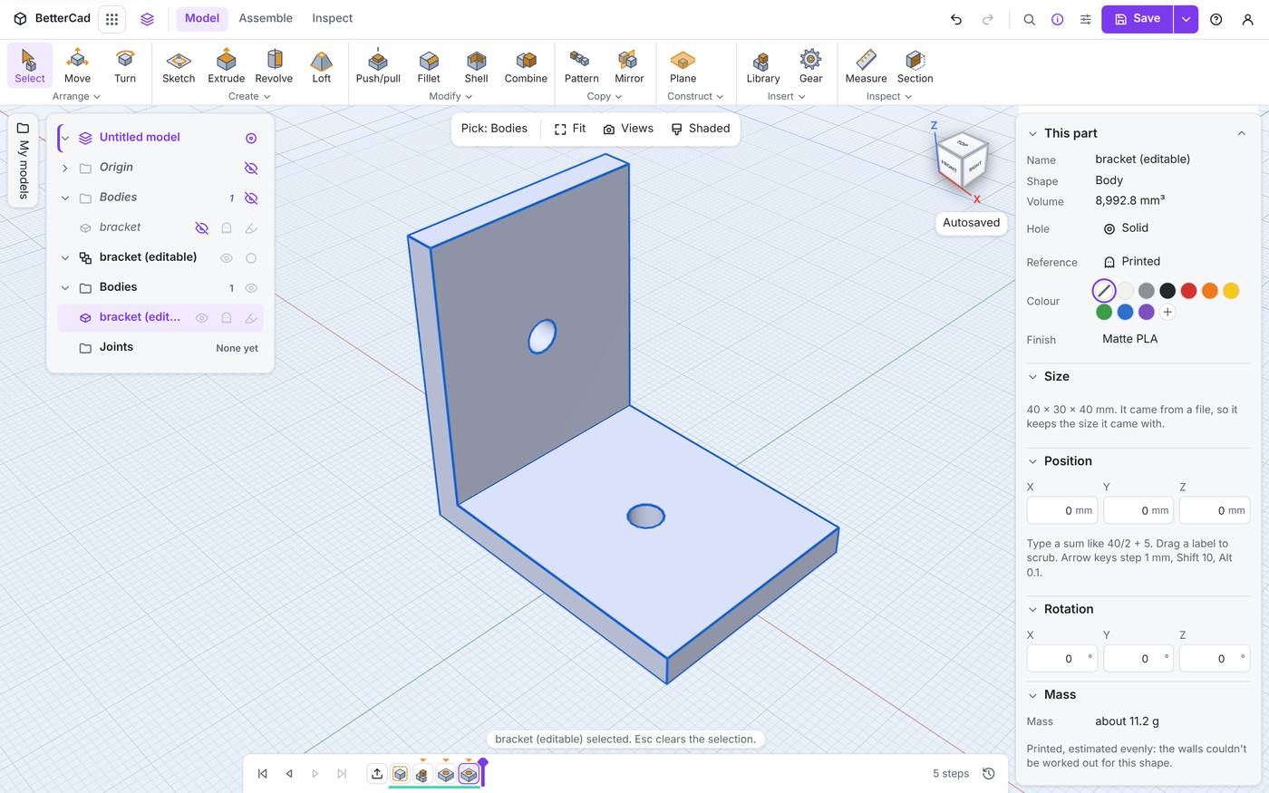
BetterCad says “bracket is now editable, with 2 holes you can change. The mesh is hidden.”
What you get
Look at the Browser and the timeline.
- A new body, bracket (editable). It’s a real solid now.
- The original mesh is still in the model with its eye switched off, in case you need it.
- A Convert step, and a Hole step for the holes it found. Holes of the same size are grouped into one step.
Those Hole steps are the ordinary kind from Learn BetterCad. Right-click one and edit it:
- Change Size from M4 to M3
- Add a countersink or a counterbore
- Move a hole, or delete the step and the hole is gone
And because the body is a true solid, it now accepts Fillet, Chamfer and Shell, which a mesh refuses.
What it can find
This is the first release of the feature, and it’s upfront about its limits.
| In the mesh | Result |
|---|---|
| A hole right through, or a blind hole with a flat bottom | Becomes a Hole step |
| A counterbore or countersink, on a clean mesh | Becomes a Hole step with that head |
| A hole with a pointed drill bottom | Becomes a Hole step with a flat bottom |
| A hole that starts on a curved or sloping face | Listed with the reason, and left alone |
| A “hole” with six sides or fewer | Left alone. That’s a pocket |
| Rounded edges and other curved faces | Counted in the summary, left as facets |
Rough meshes
Not every STL is clean. Files that have been repaired, simplified or scanned have wobbly holes. The Mesh setting at the top of the panel has three levels: Clean, Rough and Very rough. Each allows more slack when deciding whether a ring of triangles is a hole.
Start on Clean. If holes you can plainly see aren’t listed, step down.
Two things stop it altogether:
- A mesh with gaps in its skin is refused. Repair it in your slicer first, then import the repaired file.
- A mostly sculpted model, like a figurine, gets a note that there’s little to find. This tool is for mechanical parts.
When to use it
Recognise features is perfect for the everyday case: a bracket, mount or case from a model site whose holes are wrong for your screws.
If you want to change the part’s overall shape, it’s usually quicker to bring the STL in as a reference and draw a fresh part over it, using Measure and sketch snapping to copy the dimensions you want to keep.
Try it Yourself
- Convert the bracket, then edit its Hole step and change both holes to M3.
- Add a 2 mm fillet to an outside edge of the editable bracket.
- Find a simple bracket STL of your own and run Recognise features on it. How many holes does it find on Clean? On Rough?
Common Issues
Problem: A hole I can see isn’t in the list. Solution: Change Mesh to Rough or Very rough. Why: Coarse or repaired meshes have holes that aren’t quite round.
Problem: BetterCad refuses the mesh. Solution: Open the STL in your slicer, repair it, export it and import that file. Why: Recognition needs a mesh without gaps.
Problem: I can’t find the original mesh after converting. Solution: It’s in the Browser with its eye off. Click the eye to show it. Why: Convert hides the mesh so you aren’t looking at two copies at once.
Check your understanding
Quick quiz 1 of 3
Why can’t you normally resize a hole in an STL?
Quick quiz 2 of 3
What does Convert make?
Quick quiz 3 of 3
Holes you can see aren’t being found on a repaired mesh. What do you try?
You can use the arrows ← → on your keyboard to navigate between lessons.
Comments