Bores, Hubs and Small Gears
Fit a 3D printed gear to a motor shaft or servo horn in BetterCad, and fix weak small gears with profile shift
By Kevin McAleer, 6 Minutes
Page last updated November 21, 2026

A gear is no use until it’s fixed to something that turns. This lesson covers the hole in the middle, the collar round it, and what goes wrong when a gear gets very small.
Four kinds of bore
Open a gear’s panel and look at Bore.
| Bore | What you get | Use it for |
|---|---|---|
| None | A solid gear | A gear you’ll join to another printed part |
| Round | A plain round hole, 5 mm to start | A gear that spins freely on an axle or a screw |
| D-flat | A round hole with one flat side | A motor shaft with a flat, such as an N20’s |
| Servo horn | A hub hole and four small arm holes | Bolting the gear to a servo’s horn |
D-flat
Small gear motors have a 3 mm shaft with a flat ground on one side so the gear can’t spin on it. Choose D-flat and two boxes appear: Bore, the shaft’s diameter, and Flat from centre, how far the flat is from the middle of the shaft.
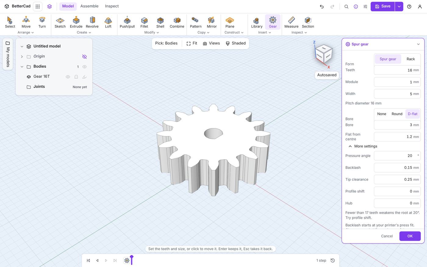
The defaults, 3 mm and 1.2 mm, are a starting point for a small gear motor. Measure yours across the round and across the flat. The flat’s distance from the centre is the across-the-flat measurement minus half the diameter.
Servo horn
This is the horn mount from lesson 6, built into the gear. Horn hub is the hole for the horn’s hub and Arm holes sets how far out the four M2 holes sit.
There’s a catch on small gears. The arm holes have to land in solid plastic, inside the bottom of the teeth. Try it on a 12-tooth module 1 gear and the panel warns “Put the horn’s arm holes inside the gear’s root”. Use more teeth, a bigger module, or a smaller Arm holes value. The project uses 24 teeth, which leaves plenty of room.
More settings
Click More settings to open the rest of the panel.
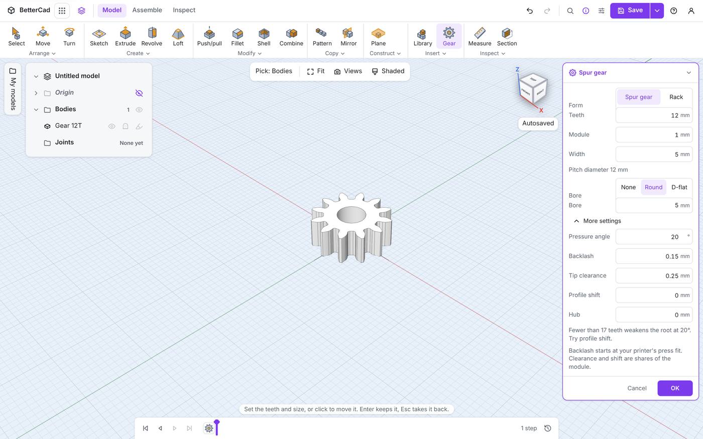
| Setting | Starts at | What it does |
|---|---|---|
| Pressure angle | 20° | The slope of the tooth. Leave it at 20 unless you’re matching a bought gear |
| Backlash | Your press fit | Thins each tooth slightly so the pair doesn’t bind |
| Tip clearance | 0.25 | The gap between one gear’s tips and the other’s roots |
| Profile shift | 0 | Moves the tooth shape outward. See below |
| Hub | 0 | The diameter of a collar on top, round the bore |
The note under them explains two of the units: “Backlash starts at your printer’s press fit. Clearance and shift are shares of the module.”
Backlash
A perfect gear pair with no slack would jam the moment your printer laid down a slightly fat line. Backlash shaves a little off every tooth. It starts at your printer’s press fit, 0.15 mm on a fresh profile, and since both gears get it, the pair has twice that between them.
If printed gears feel tight, raise it. If a mechanism has too much slop, lower it.
Hub
Type a diameter into Hub and a collar grows on top of the gear, with a Hub length box for its height.
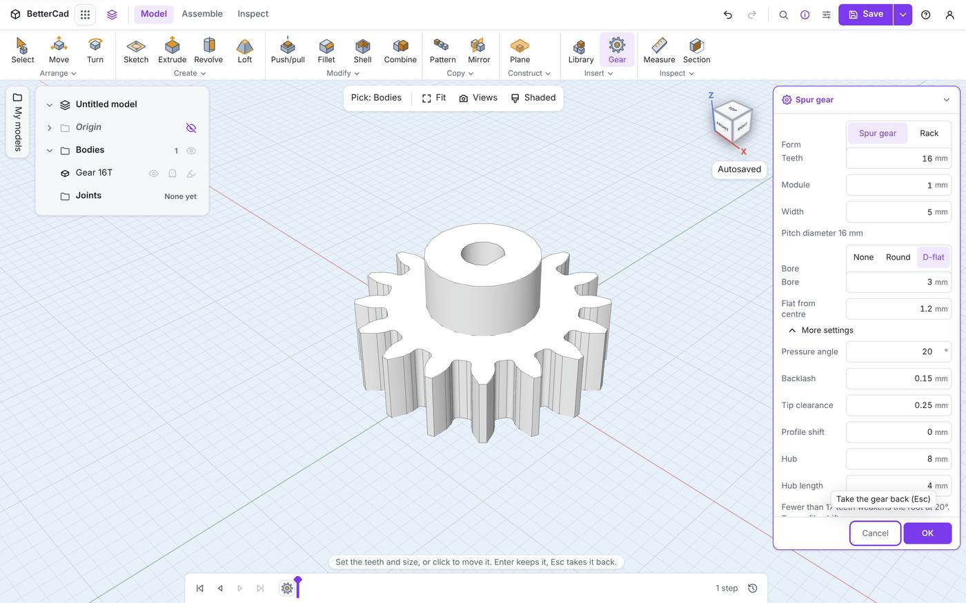
A hub gives the shaft more to grip, and somewhere to put a grub screw. Make it comfortably wider than the bore.
Small gears and undercut
Set Teeth to 12 and a warning appears: “Fewer than 17 teeth weakens the root at 20°. Try profile shift.”
Here’s why. On a gear with few teeth, the correct tooth curve cuts into the base of the tooth itself and leaves it narrow-waisted. That’s called undercut, and it makes the teeth snap off just where the load is highest.
Profile shift is the cure. It moves the tooth shape outward, away from the centre, so the base stays thick.
- With 12 teeth showing the warning, set Profile shift to
0.4.
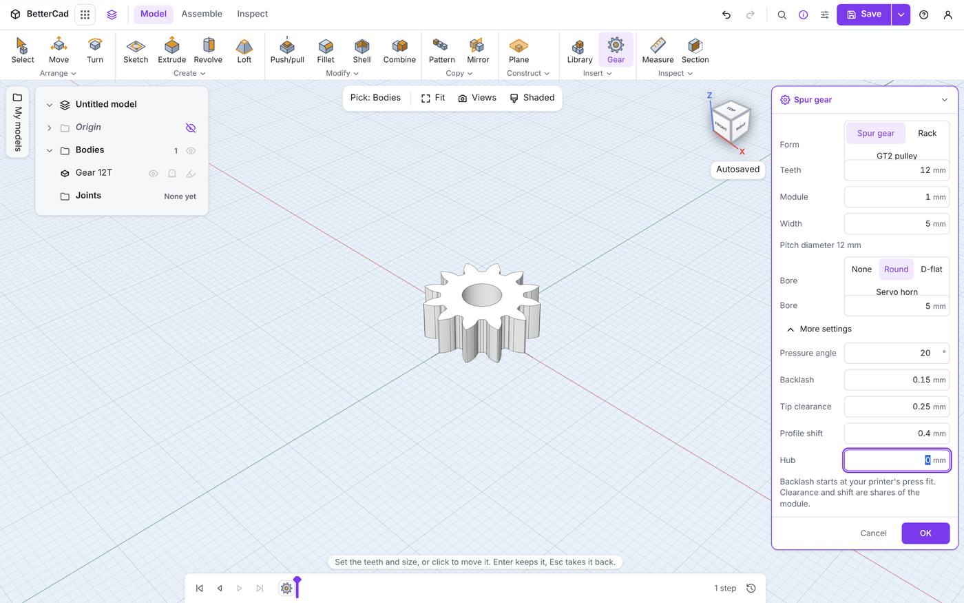
The teeth look stubbier and stronger. Values from 0.3 to 0.5 suit most small gears.
A shifted gear is a little bigger than its numbers suggest, so it sits slightly further from its partner. You don’t have to work that out: when you mesh gears in the next lesson, BetterCad allows for the shift.
The simplest fix of all is to avoid the problem. If there’s room, use 17 teeth or more.
Try it Yourself
- Make a 16-tooth gear with a D-flat bore for a 3 mm shaft.
- Add a hub 8 mm across and 5 mm long.
- Drop it to 10 teeth and add profile shift until the teeth look sturdy. What value did you settle on?
Common Issues
Problem: The gear disappears and BetterCad says it rebuilt with a problem. Solution: Undo the last change, then make the hub wider or the bore smaller. Why: Some combinations can’t be built. A 4 mm hub round a 3 mm D-flat bore is one: the wall between them is too thin.
Problem: The D-flat gear is loose on the motor shaft. Solution: Reduce Bore by 0.1 mm at a time, or reduce Flat from centre. Why: A drive bore wants to be a push fit, tighter than a hole for a screw.
Problem: My two printed gears bind at one point in each turn. Solution: Raise Backlash on both, and check the first layer isn’t squashed outward. Why: A flared first layer, often called elephant’s foot, makes the teeth fat at the bottom.
Check your understanding
Quick quiz 1 of 3
Which bore suits a small gear motor’s shaft?
Quick quiz 2 of 3
What does profile shift fix?
Quick quiz 3 of 3
Two meshing gears each have a backlash of 0.15 mm. How much slack is there between them?
You can use the arrows ← → on your keyboard to navigate between lessons.
Comments