Summary and Next Steps
Review what you learned about joints, poses, clash checks, drive links and URDF in BetterCad and find out where to go next
By Kevin McAleer, 4 Minutes
Page last updated November 21, 2026

You started with three flat bars on a print bed. You finish with an arm that bends at two joints, knows its own weight and limits, can’t be driven into itself, and can be handed to a simulator in one file.
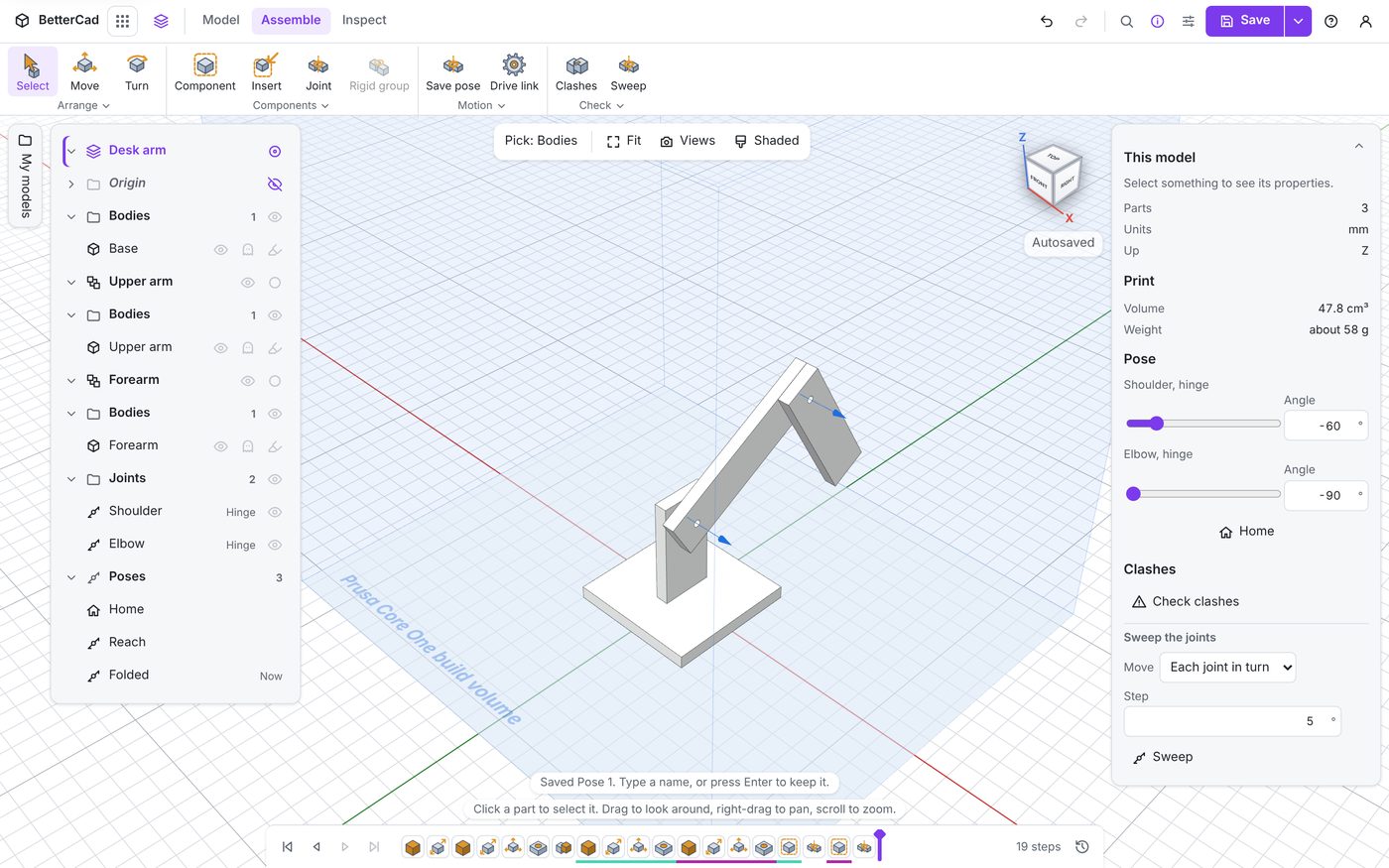
If you’d like to compare, here is my finished arm: desk-arm.bcad. The servo deck with its drive link is here: servo-deck-drive.bcad.
What you learned
| Topic | The short version |
|---|---|
| Components | A group of bodies that move as one. The Joint tool makes them for you |
| Joints | Two clicks: a snap on the part that moves, then a snap on what it hangs from |
| Posing | Slider, typed angle or drag. Home is where each joint was made |
| Chains | A part moves with every joint between it and Base |
| Kinds | Hinge, Wheel, Slider and Fixed, which URDF calls revolute, continuous, prismatic and fixed |
| Line-up | Angle, Gap, offsets and Flip set where a joint rests |
| Named poses | Save the joint angles that matter and go back in a click |
| Tool point | Drag the arm by its tip and the joints work themselves out |
| Mass | Printed estimate or datasheet weight, with a centre of mass for each moving part |
| Clash check | Finds overlaps and touches in one pose |
| Sweep | Runs joints through their range, reports where parts hit, and sets safe limits |
| Drive links | One joint drives another through gears, a belt, a rack or a ratio |
| URDF | Links, joints, meshes, masses and limits in one zip |
A workflow worth keeping
- Design the parts with a hole wherever a joint will go.
- Make each joint at a sensible home pose, and name it straight away.
- Set limits from your hardware.
- Save the poses you care about.
- Sweep. Fix what hits, or tighten the limits.
- Check the heaviest pose against your servo’s torque.
- Print.
Steps 5 and 6 are the ones that save filament.
Try it Yourself
- Add a wrist. Design a small gripper plate, joint it to the tip of the forearm, and move the tool point onto it.
- Fit real servos. Drop an SG90 from the robot catalogue into the base and the upper arm, cut their pockets, and re-run the sweep with Reference bodies ticked.
- Gear the shoulder. Put a 2 : 1 gear pair between a servo and the shoulder, add the drive link, and work out how much more the arm can now lift.
- Build a rover. Four wheel joints, linked with Link joints, on a chassis plate.
What’s Next
- Design Robot Parts with BetterCad if you came here first. It covers the catalogue, pockets, mounts and the gears from the drive links lesson
- Print It Right with BetterCad to make sure the holes your joints rely on come out the right size
- Learn ROS with me to put your URDF to work
- Wire It Up - Electronics in Snakie to wire the servos to a Pico
- Getting Started with Snakie to write the MicroPython that moves them to the angles in your poses
Both BetterCad courses for robot builders are in the BetterCad for Robot Builders pathway.
And for build videos, robot projects and livestreams, subscribe to Kevin McAleer on YouTube.
Check your understanding
Quick quiz 1 of 3
You’ve changed the shape of the upper arm. Which check should you run again before printing?
Quick quiz 2 of 3
Which of these is saved in a URDF export?
Quick quiz 3 of 3
What is the quickest way to find the joint angles that put the tip at a certain spot?
You can use the arrows ← → on your keyboard to navigate between lessons.
Comments