Project - An Obstacle-Avoiding Robot
Wire a two-wheeled robot in Snakie, check it, print its build guide, and program it in MicroPython to drive forward and turn away from walls
By Kevin McAleer, 8 Minutes
Page last updated November 20, 2026

You’ve met every tool. Now let’s use them in order, the way you would on a real project: plan, wire, check, document, code, build.
The robot is the classic first one. Two wheels, one distance sensor. It drives forward until something is closer than 30 cm, then spins on the spot until the way is clear.
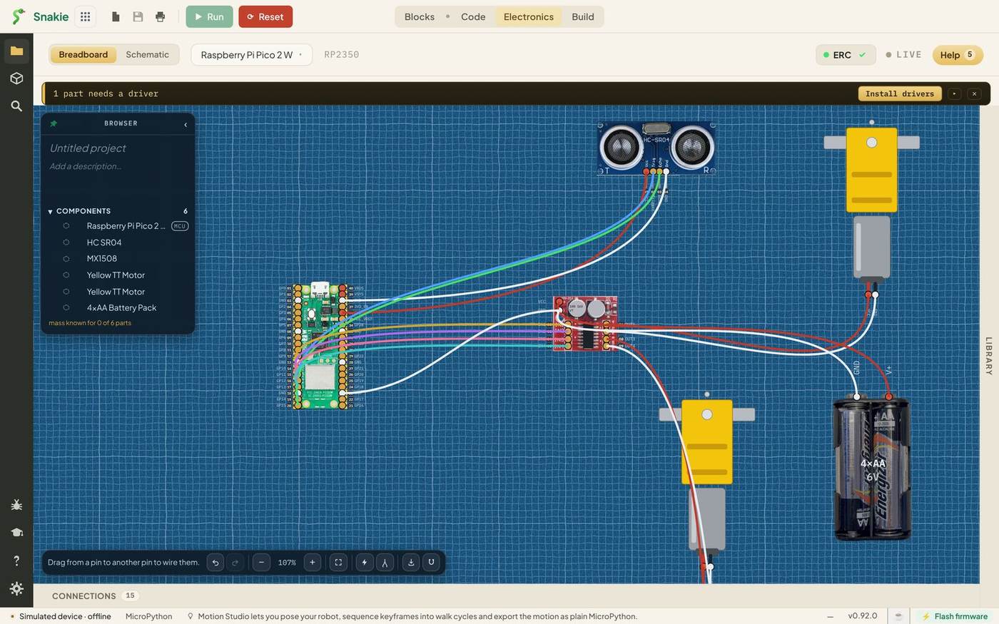
If you’ve been following along, most of this is already on your canvas. Treat this lesson as the checklist.
Step 1: Gather the parts
In a new Electronics project, name it Obstacle Robot and add:
| Qty | Part | Job |
|---|---|---|
| 1 | Raspberry Pi Pico 2 W | The brain. Already on the canvas |
| 1 | HC SR04 | Measures the distance ahead |
| 1 | MX1508 | Switches battery power to the motors |
| 2 | Yellow TT Motor | One for each wheel |
| 1 | 4×AA Battery Pack | Power for the motors |
Arrange them with the Pico on the left, the sensor above, the driver in the middle and the motors and battery to the right.
Step 2: Wire it
Fifteen wires. Tick them off as you go.
| # | From | To | Kind |
|---|---|---|---|
| 1 | HC SR04 VCC | Pico 3V3 | Power |
| 2 | HC SR04 GND | Pico GND | Ground |
| 3 | HC SR04 Trigger | Pico GP14 | Signal |
| 4 | HC SR04 Echo | Pico GP15 | Signal |
| 5 | MX1508 IN1 | Pico GP10 | Signal |
| 6 | MX1508 IN2 | Pico GP11 | Signal |
| 7 | MX1508 IN3 | Pico GP12 | Signal |
| 8 | MX1508 IN4 | Pico GP13 | Signal |
| 9 | MX1508 OUT1 | Left motor, first terminal | Motor |
| 10 | MX1508 OUT2 | Left motor, second terminal | Motor |
| 11 | MX1508 OUT3 | Right motor, first terminal | Motor |
| 12 | MX1508 OUT4 | Right motor, second terminal | Motor |
| 13 | Battery V+ | MX1508 VCC | Power |
| 14 | Battery GND | MX1508 GND | Ground |
| 15 | Pico GND | MX1508 GND | Shared ground |
Step 3: Check it
- The ERC badge should show a green tick.
- The count beside Connections should be 15.
- Open the Connections table and read it against the table above.
- Switch on node voltages and check the battery’s supply reaches the MX1508.
Step 4: Install the driver
Click Install drivers on the banner so hcsr04.py is on the board.
Step 5: Document it
Click the printer button and save the PDF build guide. Print the Connections page. You’ll want it beside you when you build.
Step 6: The code
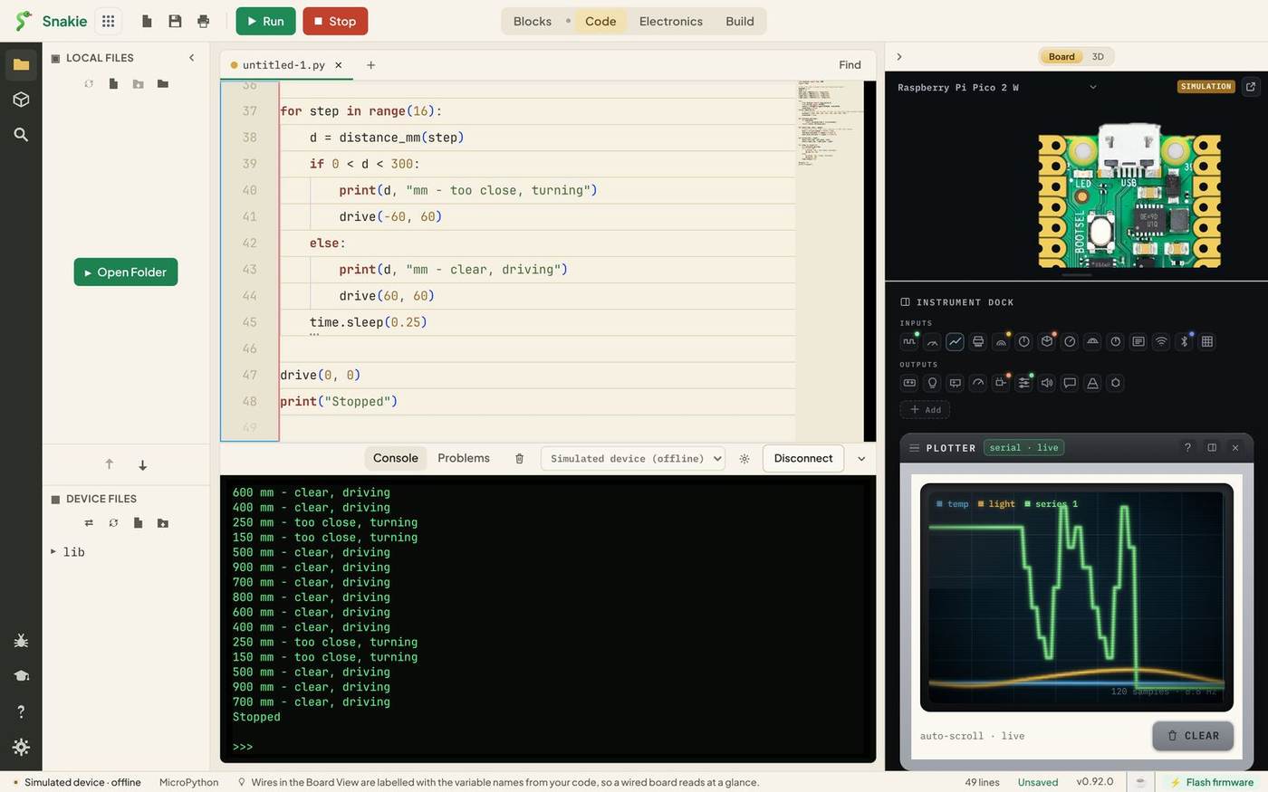
Here’s the complete program. Run it right here first.
In the simulator the console shows the robot making its decisions:
800 mm - clear, driving
600 mm - clear, driving
400 mm - clear, driving
250 mm - too close, turning
150 mm - too close, turning
500 mm - clear, driving
How it works
The pins. The first block sets up the six pins. Every number comes from the Connections table. If you move a wire, this is the only place the code has to change.
Real or pretend. The simulator can run motors’ signals, but it can’t time a real echo. So the program checks whether time_pulse_us exists. On a real Pico it does, and the driver is used. In the simulator it doesn’t, so the program plays back a list of pretend distances. That lets you test the decision-making with no hardware at all.
motor() turns a speed from -100 to 100 into PWM on the right pin. Positive speeds drive the forward input, negative speeds drive the backward input, and the other input is always switched off.
drive() sets both motors at once. drive(60, 60) goes straight. drive(-60, 60) runs the left wheel backwards and the right wheel forwards, which spins the robot on the spot.
The loop reads the distance and chooses. The test is 0 < d < 300, not just d < 300, because the sensor returns -1 when it hears no echo at all. No echo means nothing is near, so the robot should keep driving.
The loop runs 16 times and stops, which is polite for a first test on a desk. For a robot that keeps going, change for step in range(16): to while True: and count the steps yourself.
Step 7: Build it for real
- Follow the Connections page of your PDF, one wire at a time, with everything unpowered.
- Prop the robot up so its wheels are off the desk.
- Plug the Pico in by USB and run the program from Snakie.
- Put your hand in front of the sensor. The wheels should change direction.
- Only then put it on the floor and let it go.
If a wheel turns the wrong way, swap that motor’s two wires at the driver. If the robot spins when it should go straight, one motor is reversed.
Make it yours
- Slow down near walls. Drive at a speed that depends on the distance
- Back up first. Reverse for a moment before turning
- Turn a random way. Pick left or right with
random.choice - Watch it think. The next course, Snakie Instruments, shows how to plot the distance live while the robot runs
Try it Yourself
- Change the turning distance from 300 mm to 150 mm. How does the console output change?
- Add your own numbers to the
pretendlist to test a robot stuck in a corner. - Challenge: make the robot reverse for half a second before it turns.
Common Issues
Problem: ImportError: no module named 'hcsr04' on a real Pico.
Solution: Click Install drivers in the Electronics workspace.
Why: The driver file has to be in the board’s lib folder.
Problem: The Pico resets when the motors start. Solution: Check the battery’s V+ goes to the MX1508’s VCC, and that the Pico’s ground is joined to the driver’s ground. Why: Motors pull a lot of current when they start. They need their own supply and a shared ground.
Problem: The distance is always -1. Solution: Check Trigger and Echo aren’t swapped, and that the sensor has power. Why: -1 means the sensor never heard an echo.
Problem: The motors hum but don’t turn. Solution: Fit fresh batteries, or raise the speed from 60. Why: A TT motor needs a certain amount of power just to get going.
Check your understanding
Quick quiz 1 of 3
Why does the program test 0 < d < 300 and not just d < 300?
Quick quiz 2 of 3
What does drive(-60, 60) do?
Quick quiz 3 of 3
Why test with the wheels off the desk first?
You can use the arrows ← → on your keyboard to navigate between lessons.
Comments