Drivers, Help and Code
Install a part's MicroPython driver from Snakie's Electronics workspace, read its built-in help page, and write code that matches your wiring
By Kevin McAleer, 6 Minutes
Page last updated November 20, 2026

A wired circuit does nothing until code runs on it. This lesson is about the bridge between the two: drivers, the help that ships with each part, and code that uses the pins you actually wired.
What a driver is
To measure a distance, the HC SR04 needs a 10 microsecond pulse on Trigger, then the length of the answering pulse on Echo has to be timed and turned into millimetres. You could write that yourself. Or you could use a driver: a small Python file, written once, that does it for you.
With a driver the whole job becomes two lines:
sensor = HCSR04(trigger=14, echo=15)
print(sensor.distance_mm())
The driver has to be on the board before your program can import it.
The driver banner
Since you added the sensor, a banner has been sitting above the canvas: 1 part needs a driver. Click the small arrow beside Install drivers to see what it means.
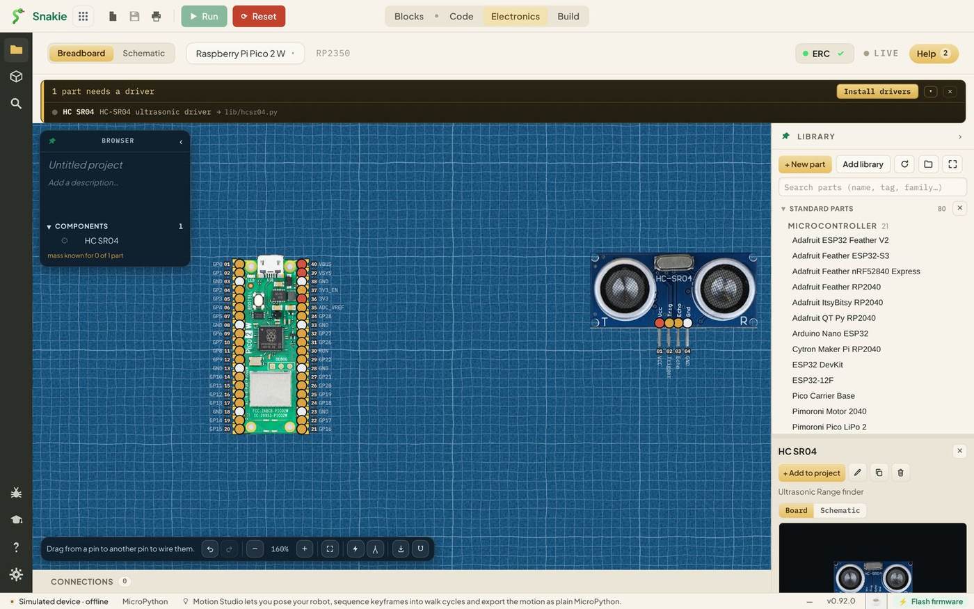
It lists the part, the driver, and where the file will go: lib/hcsr04.py.
Click Install drivers. Snakie copies the file to the board and the banner disappears. Look in Device Files in the Code workspace and you’ll find a new lib folder with the driver inside.
Three things worth knowing:
- Nothing is copied until you click. Snakie asks first
- The banner checks the board, so it only lists drivers that are missing or out of date
- It works on the simulated device too, so you can try it with no board plugged in
The motors, the battery and the MX1508 have no driver. They don’t need one, because the Pico controls the MX1508 with ordinary pin signals.
Help for every part
Select the MX1508 and click the ? on its toolbar.
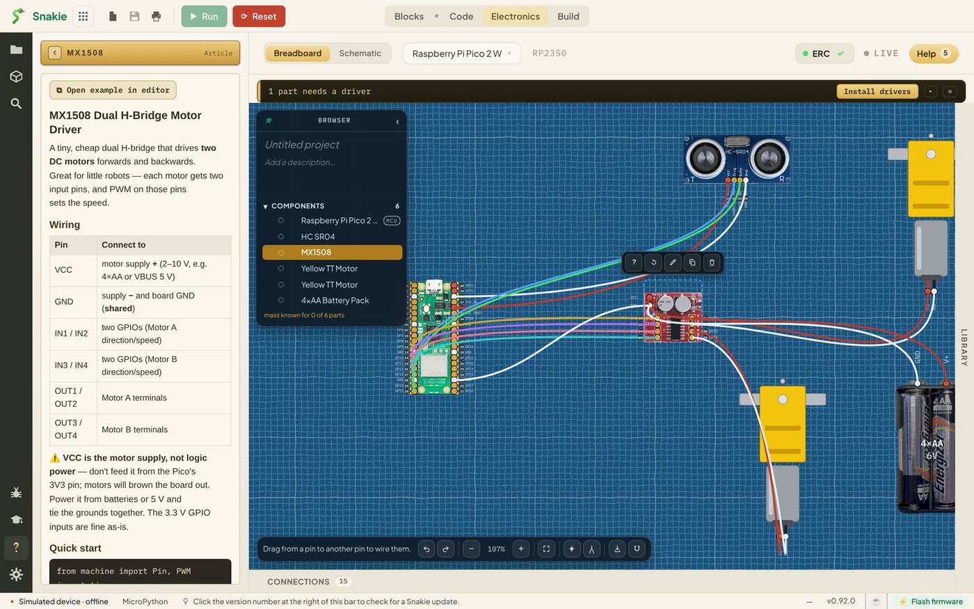
A help page opens beside your wiring. Each one follows the same pattern:
- What the part is and what it’s good for
- A wiring table: which pin goes where
- Warnings about the mistakes people really make
- A Quick start program
- An Open example in editor button that drops that program into a new file
Read the warning on this one: VCC is the motor supply, not logic power. Don’t feed it from the Pico’s 3V3 pin; motors will brown the board out. That’s exactly why our battery goes to the driver and nowhere else.
The Help button at the top right of the workspace counts how many of your parts have a page like this.
Code that matches the wiring
Here’s a first program for the motor driver. It ramps the left motor up and down without touching the sensor.
Press Run. In the simulator you’ll see the percentages count up. On a real robot, the left wheel speeds up in five steps and stops.
Look at the comment on line 4. GP10 and GP11 aren’t numbers picked at random. They’re the pins you wired to IN1 and IN2 in lesson 4. This is the whole idea of the Electronics workspace: the wiring diagram is the source of your pin numbers.
How the motor driver works
Each motor has two inputs.
| IN1 | IN2 | The motor |
|---|---|---|
| On | Off | Turns forwards |
| Off | On | Turns backwards |
| Off | Off | Coasts to a stop |
| On | On | Brakes |
Instead of fully on, we send PWM: the pin flicks on and off a thousand times a second, and duty_u16 sets how much of the time it’s on. More on-time means more speed. 65535 is flat out and 0 is stopped.
Blocks know your wiring too
If you prefer blocks, switch to the Blocks workspace and open the My parts drawer. Parts you’ve wired get a shelf of their own there, with the pins already filled in from this diagram. The My Parts lesson in the Snakie Blocks course shows how it works.
Try it Yourself
- Change the motor test to drive the right motor. Which two pin numbers do you need?
- Make the left motor run backwards at half speed for two seconds.
- Open the HC SR04’s help page and read its Tips. What does a reading of -1 mean?
Common Issues
Problem: ImportError: no module named 'hcsr04'
Solution: Go back to Electronics and click Install drivers.
Why: The driver file isn’t on the board yet.
Problem: Install drivers is greyed out. Solution: Connect a board, or choose the simulated device. Why: Installing copies a file to a device, so there has to be one.
Problem: The wrong wheel turns. Solution: Check the pin numbers in your code against the Connections table. Why: The code does exactly what the numbers say, even when the numbers are for the other motor.
Check your understanding
Quick quiz 1 of 3
What is a driver?
distance_mm().Quick quiz 2 of 3
Why does the MX1508’s VCC go to the battery and not to the Pico’s 3V3 pin?
Quick quiz 3 of 3
Where should the pin numbers in your code come from?
You can use the arrows ← → on your keyboard to navigate between lessons.
Comments