Wiring with Noodles
Draw wires between pins in Snakie, understand power, ground and signal connections, and wire a distance sensor and a motor driver to a Pico
By Kevin McAleer, 6 Minutes
Page last updated November 20, 2026

Snakie’s wires are soft, curved and colourful, a bit like noodles. Drawing one takes a single drag.
Your first wire
The sensor needs power. Find the sensor’s VCC pin and the Pico’s 3V3 pin (pin 36, on the right-hand side).
- Put the pointer on the sensor’s VCC dot.
- Hold the mouse button and drag to the Pico’s 3V3 dot.
- Let go.
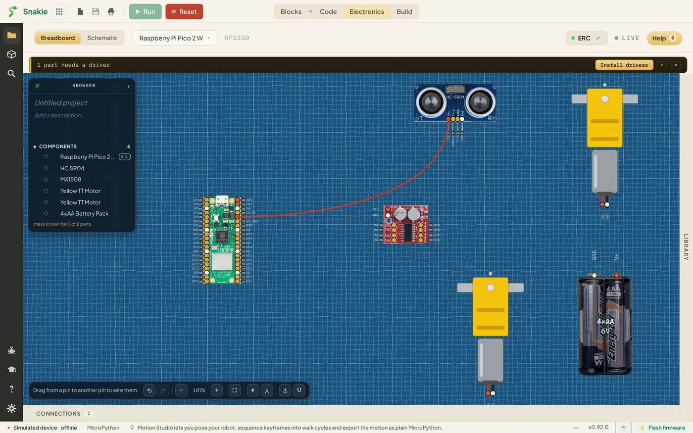
A red wire joins the two pins, and the count beside Connections at the bottom goes up to 1. It doesn’t matter which end you start from.
Hover over a pin and Snakie shows what that pin can do, so you can check before you drag.
Power, ground and signal
Every part in this robot needs three kinds of connection.
Power brings electricity to the part. The sensor takes it from the Pico’s 3V3 pin.
Ground is the way back. Electricity flows in a loop, so a part with power and no ground does nothing at all. Every ground in a circuit must be joined to every other ground.
Signals carry information between the part and a GPIO pin on the Pico. Your code reads and writes these.
Snakie colours wires to match: red for power, white for ground, and a different colour for each signal so you can follow them.
Finish the sensor
Add three more wires:
| From | To |
|---|---|
| HC SR04 GND | Pico GND (pin 38) |
| HC SR04 Trigger | Pico GP14 |
| HC SR04 Echo | Pico GP15 |
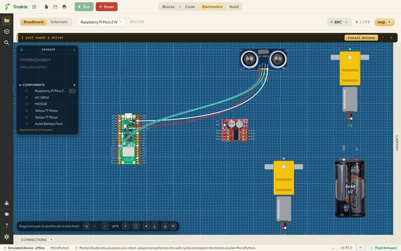
Four wires, and the sensor is done. Trigger and Echo could go to almost any GPIO pin. We’ve picked GP14 and GP15 because they’re next to each other and near the bottom of the board.
Fixing a wire
Click a wire to select it.
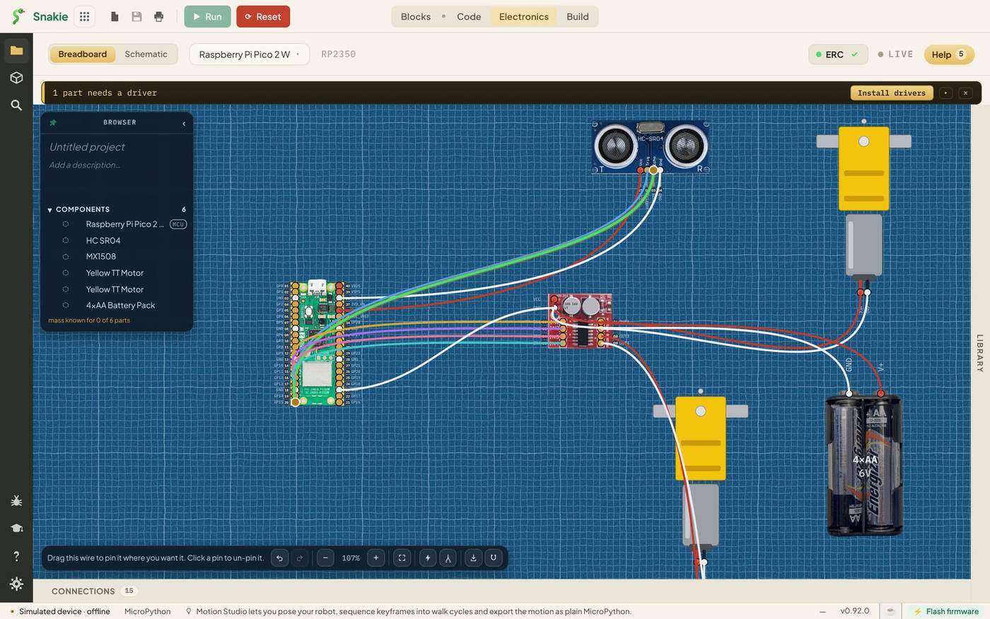
The hint in the toolbar changes to Drag this wire to pin it where you want it. Click a pin to un-pin it. Dragging the middle of a selected wire reshapes it, which is how you untangle a crowded diagram. A selected wire also offers a colour picker and a delete button.
And if a wire lands on the wrong pin, Ctrl+Z takes it back. Ctrl+Y redoes it. The two arrow buttons in the toolbar do the same.
Wire the motor driver’s inputs
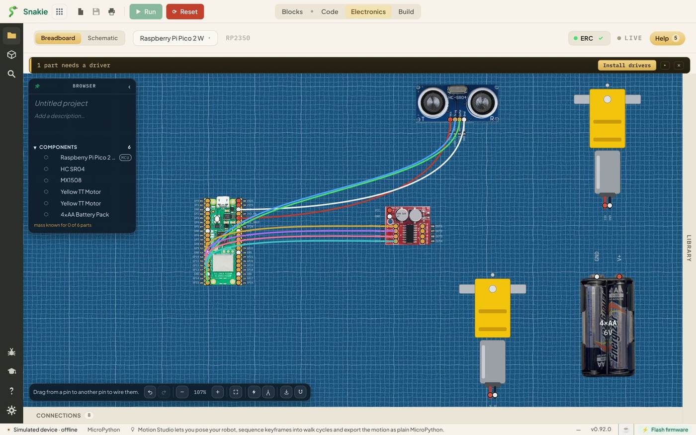
A Pico pin can’t run a motor. It can only supply a trickle of current, and a motor wants a flood. The MX1508 motor driver sits in between: the Pico tells it what to do on four thin signal wires, and the driver switches battery power to the motors.
| From | To | Controls |
|---|---|---|
| MX1508 IN1 | Pico GP10 | Left motor forwards |
| MX1508 IN2 | Pico GP11 | Left motor backwards |
| MX1508 IN3 | Pico GP12 | Right motor forwards |
| MX1508 IN4 | Pico GP13 | Right motor backwards |
Motors and battery
Now the heavy side. Each motor has two terminals, and each pair goes to a pair of outputs on the driver:
| From | To |
|---|---|
| MX1508 OUT1 and OUT2 | The two terminals of the left motor |
| MX1508 OUT3 and OUT4 | The two terminals of the right motor |
| Battery V+ | MX1508 VCC |
| Battery GND | MX1508 GND |
| Pico GND (pin 23) | MX1508 GND |
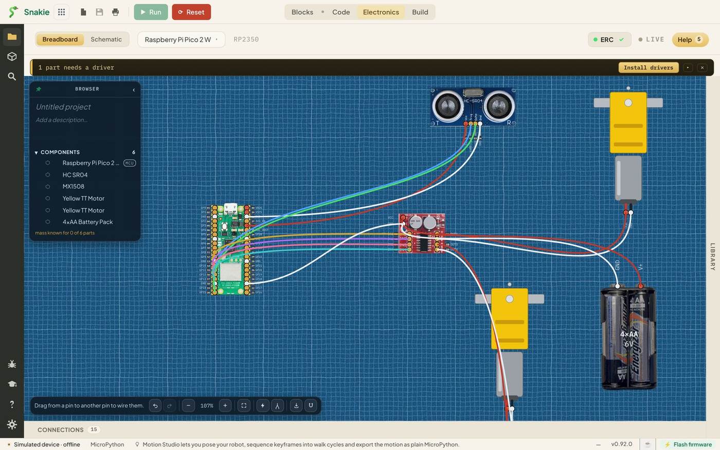
Fifteen connections, and the robot is wired.
Look at the last row of the table again. It joins the Pico’s ground to the driver’s ground, which is also the battery’s ground. That one white wire is the shared ground, and it’s the wire beginners most often leave out. Without it, the Pico’s signals have nothing to be measured against and the motors do nothing, or twitch at random.
Notice what we did not do: the battery’s V+ goes only to the motor driver. The Pico is powered from its USB cable. Four fresh AA cells give about 6 V, which is more than a Pico’s VSYS pin is rated for.
Try it Yourself
- Select the Trigger wire and change its colour.
- Reshape two wires that cross so they’re easier to follow.
- Delete the shared ground wire, then put it back with undo. Does the Connections count change both times?
Common Issues
Problem: The part moves when I try to draw a wire. Solution: Start the drag exactly on the pin’s dot. Zoom in if the pins are small. Why: A drag that starts on a dot makes a wire. Anywhere else on the part moves it.
Problem: My wire went to the pin next door. Solution: Undo, zoom in, and try again. Hover first to check you’re on the right pin. Why: A Pico’s pins are close together, and at low zoom a small slip lands on a neighbour.
Problem: A motor would spin the wrong way. Solution: Swap its two wires at the driver’s outputs. Why: A DC motor’s direction depends on which way round its terminals are connected.
Check your understanding
Quick quiz 1 of 3
Why can’t a Pico pin drive a motor directly?
Quick quiz 2 of 3
What is the shared ground?
Quick quiz 3 of 3
How do you draw a wire?
You can use the arrows ← → on your keyboard to navigate between lessons.
Comments