The Schematic View
Switch a Snakie wiring project to the Schematic view, learn to read a circuit diagram, and arrange the symbols so the circuit is easy to follow
By Kevin McAleer, 5 Minutes
Page last updated November 20, 2026

The Breadboard view shows what your circuit looks like. The Schematic view shows what it does. Same circuit, same wires, drawn a different way.
Switch views
Click Schematic at the top left.
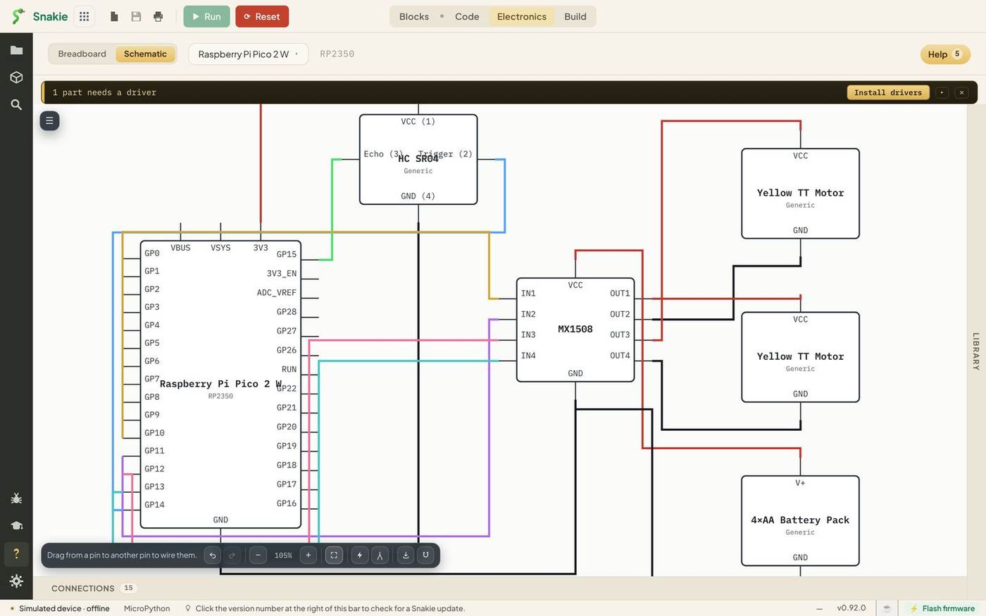
The photos are gone. Each part is now a plain box with its name in the middle and its pins around the edge. The wires are straight lines with square corners. Each signal keeps the colour it had on the breadboard, power is red and ground is black.
Nothing has been lost. Count the connections at the bottom: still 15.
Why bother with a schematic?
A breadboard picture is perfect for building. You can hold your real board beside it and copy it wire by wire.
It’s not so good for understanding. Wires curve over each other, parts hide pins, and it’s hard to see at a glance what’s joined to what.
A schematic throws away the real shapes and keeps only the connections. Engineers have drawn circuits this way for over a century, and every datasheet and repair manual uses them. Learning to read one is a skill you’ll use far beyond Snakie.
Read the robot
Follow three lines on the diagram:
- A signal. Find IN1 on the MX1508 and follow its wire back to the Pico. It ends at GP10. One wire, two ends, one job.
- Power. Find V+ on the battery pack. Its red line goes to VCC on the MX1508 and nowhere else. The battery feeds the motor driver only.
- Ground. Find the black line. It visits GND on the battery, the driver and the Pico. That’s the shared ground from the last lesson, and in the schematic you can see it joining three parts.
That third one is the big win. On the breadboard view the shared ground is three separate white wires. Here it’s obviously one thing.
Tidy the diagram
The first time you open the Schematic view, the symbols may overlap. Drag them apart, just as you dragged parts on the breadboard.
A few habits make schematics easy to read:
- Put the controller on the left
- Put the things it controls on the right
- Keep power at the top and ground at the bottom where you can
- Leave space between symbols so the lines have room
One thing to know: the two views share their positions. Move a symbol here and the part moves on the breadboard as well. Symbols and photos are different sizes, so a layout that’s neat in one view can need a nudge in the other. Arrange the view you’ll use most, and press Ctrl+Z if you change your mind.
Wire from either view
You can draw wires in the Schematic view as well. Drag from the end of one pin to the end of another. The new wire appears in the Breadboard view too, because both are pictures of the same list of connections.
Some people prefer to design in the schematic and build from the breadboard. Use whichever suits how you think.
Click Breadboard to go back.
Try it Yourself
- In the schematic, find which Pico pins go to the HC SR04’s Trigger and Echo.
- Arrange the symbols so that no two overlap and as few lines cross as you can manage.
- Switch back to Breadboard. Did your parts move? Use undo to put them back if you prefer the old layout.
Common Issues
Problem: The symbols are in a heap. Solution: Drag each one clear, then click Zoom to fit. Why: Symbols are bigger than the little boards they stand for, so parts that sat neatly apart on the breadboard can overlap here.
Problem: I can’t tell which wire is which where they cross. Solution: Follow the colour. Each signal keeps its own colour in both views. Why: Colours are tied to the connection, not to the view.
Problem: A pin I wired on the breadboard seems to be missing. Solution: Look round all four sides of the symbol. Why: Symbols group pins by job, so a pin isn’t always on the side you’d expect from the photo.
Check your understanding
Quick quiz 1 of 3
What does a schematic show that a breadboard picture doesn’t make obvious?
Quick quiz 2 of 3
You move a symbol in the Schematic view. What happens on the breadboard?
Quick quiz 3 of 3
In the robot’s schematic, where does the battery’s V+ go?
You can use the arrows ← → on your keyboard to navigate between lessons.
Comments