Connections and Measurements
Read the Connections table in Snakie, understand nets, see the voltage on every wire and probe your circuit with the on-screen multimeter
By Kevin McAleer, 5 Minutes
Page last updated November 20, 2026

A picture of a circuit is nice. A list of its connections is what you check your work against. Snakie keeps one for you, and it can do some measuring on screen as well.
The Connections table
Click Connections at the bottom of the workspace.
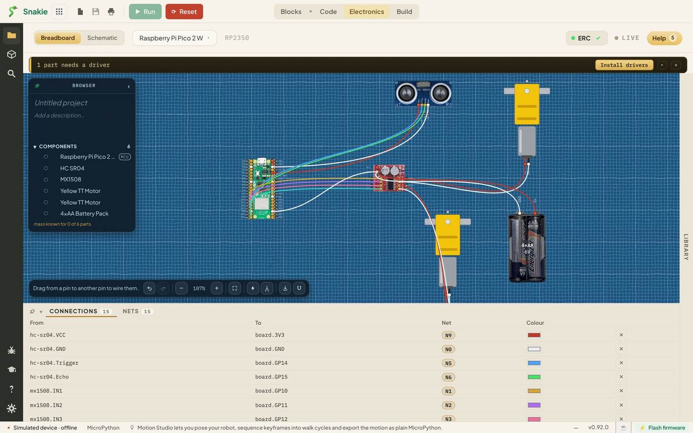
Every wire is a row:
| Column | What it shows |
|---|---|
| From | The pin the wire starts at, written part.pin |
| To | The pin it ends at |
| Net | The net this wire belongs to |
| Colour | The wire’s colour on the diagram |
| ✕ | Deletes the wire |
So hc-sr04.Trigger → board.GP14 means “the Trigger pin of the HC SR04 goes to GP14 on the board”. Read down the list and you have the whole robot in fifteen lines.
This is the best tool there is for checking a real build. Go down the table one row at a time, touch each wire on your breadboard, and you’ll find the mistake.
Nets
The Net column needs a word of explanation. A net is a set of pins that are all joined together, however many wires it takes.
Look at the three ground wires in the table. They have different ends, but all three show the same net. Electrically, the battery’s GND, the driver’s GND and the Pico’s GND are one point. That’s the shared ground, written down.
Click Nets, beside Connections, to see the circuit listed net by net.
Voltages on every wire
Because the battery pack is in the circuit, Snakie has enough to work out some real numbers. Click Show node voltages, the lightning button in the toolbar.
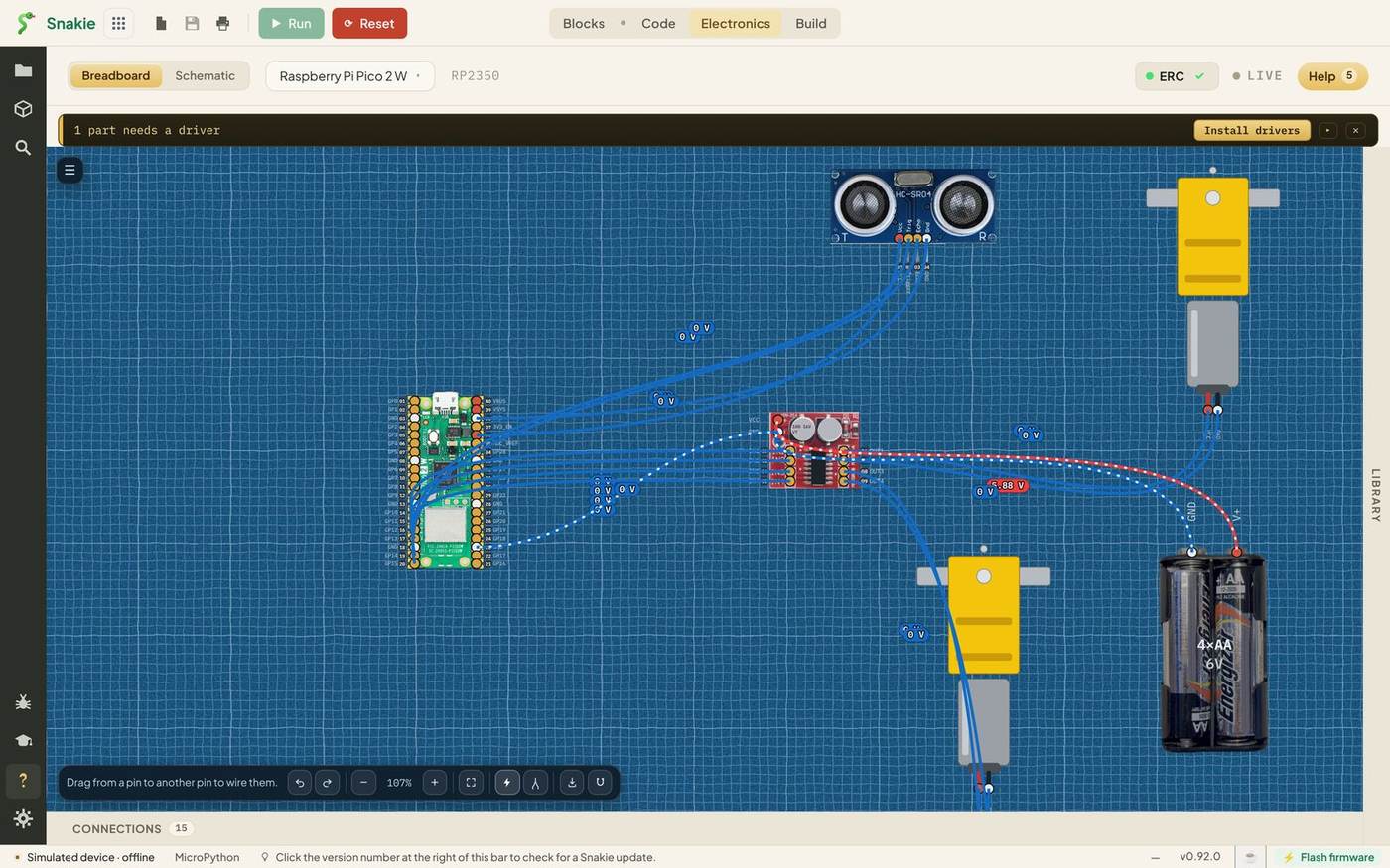
Every wire gets a small tag with its voltage, and the wires are recoloured to match: red for the battery’s 5.88 V, blue for 0 V. A moving dotted line marks the loop the current flows round, from the battery’s V+, through the motor driver and back to GND.
The sensor’s wires all read 0 V here. That isn’t a fault. The overlay only knows about the power sources on the canvas, and the Pico’s own supply comes down a USB cable that isn’t in the drawing.
If there’s nothing to work out, the hint tells you why. Nothing to solve yet means the circuit has no battery or power supply in it. No ground means the supply has no path back.
Click the button again to switch the overlay off.
The on-screen multimeter
A multimeter is the tool you’ll reach for most on a real bench. Snakie has one built in. Click the Multimeter button, next to the lightning, then click the VCC pin of the MX1508.
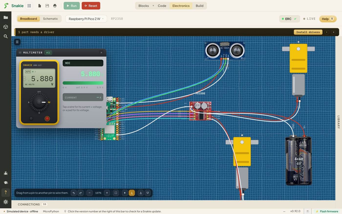
The meter reads 5.880 V. That’s what four AA cells give with a small load on them: a little under the 6 V on the label, just as a real pack would.
- Click a pin to read its voltage
- Click a wire to read the current through it as well
Try the battery’s V+ terminal, then a ground pin. Ground should read 0 V. If it doesn’t, something isn’t joined up.
Click the Multimeter button again to put it away. While it’s open, clicking a pin takes a reading and doesn’t start a wire.
These numbers come from a simulation that uses what the library knows about each part. They’re a guide to what to expect, not a replacement for measuring your real circuit.
The LIVE button
At the top right is LIVE. With a real board connected, it reads the actual state of the pins from the board and shows them on the diagram, so you can watch an input change as you press a button. It needs a connected board, and it pauses a running program each time it reads, so switch it off when you’re done.
Try it Yourself
- Find the net with the most connections in the table. Which one is it?
- Probe both terminals of the battery pack. What’s the difference between the two readings?
- Delete the shared ground wire and switch node voltages on. What changes? Undo it afterwards.
Common Issues
Problem: Node voltages says there’s nothing to solve. Solution: Add a battery or the bench power supply from the Library and wire both its terminals. Why: With no source of power there are no voltages to work out.
Problem: I can’t draw wires any more. Solution: Click the Multimeter button to switch it off. Why: While the meter is open, clicking a pin probes it.
Problem: LIVE shows nothing. Solution: Connect a real board. Why: LIVE reads real pins. The diagram alone has no live values.
Check your understanding
Quick quiz 1 of 3
What is a net?
Quick quiz 2 of 3
What does mx1508.IN1 → board.GP10 mean?
Quick quiz 3 of 3
A fresh 4×AA pack is labelled 6 V. Why does the meter show a little less?
You can use the arrows ← → on your keyboard to navigate between lessons.
Comments