Combining Parts and Holes
Add screw holes that fit on a real printer with the BetterCad Hole tool, and cut one shape out of another by grouping
By Kevin McAleer, 6 Minutes
Page last updated November 20, 2026

A box becomes a useful part when things can be screwed to it and cables can get into it. This lesson covers the two ways BetterCad makes holes: the Hole tool for screws, and hole shapes for everything else.
Screw holes that fit
Here’s something every new designer learns the hard way: draw a 3 mm hole, print it, and an M3 screw won’t go in. Printed holes come out small. BetterCad’s Hole tool knows this, so you pick the screw and it works out the hole.
Press Hole (H), click a face where you want each hole, choose the screw size and press Enter.
With the 60 × 40 × 30 mm box from the last lesson:
- Press H.
- Click the top face, near a corner.
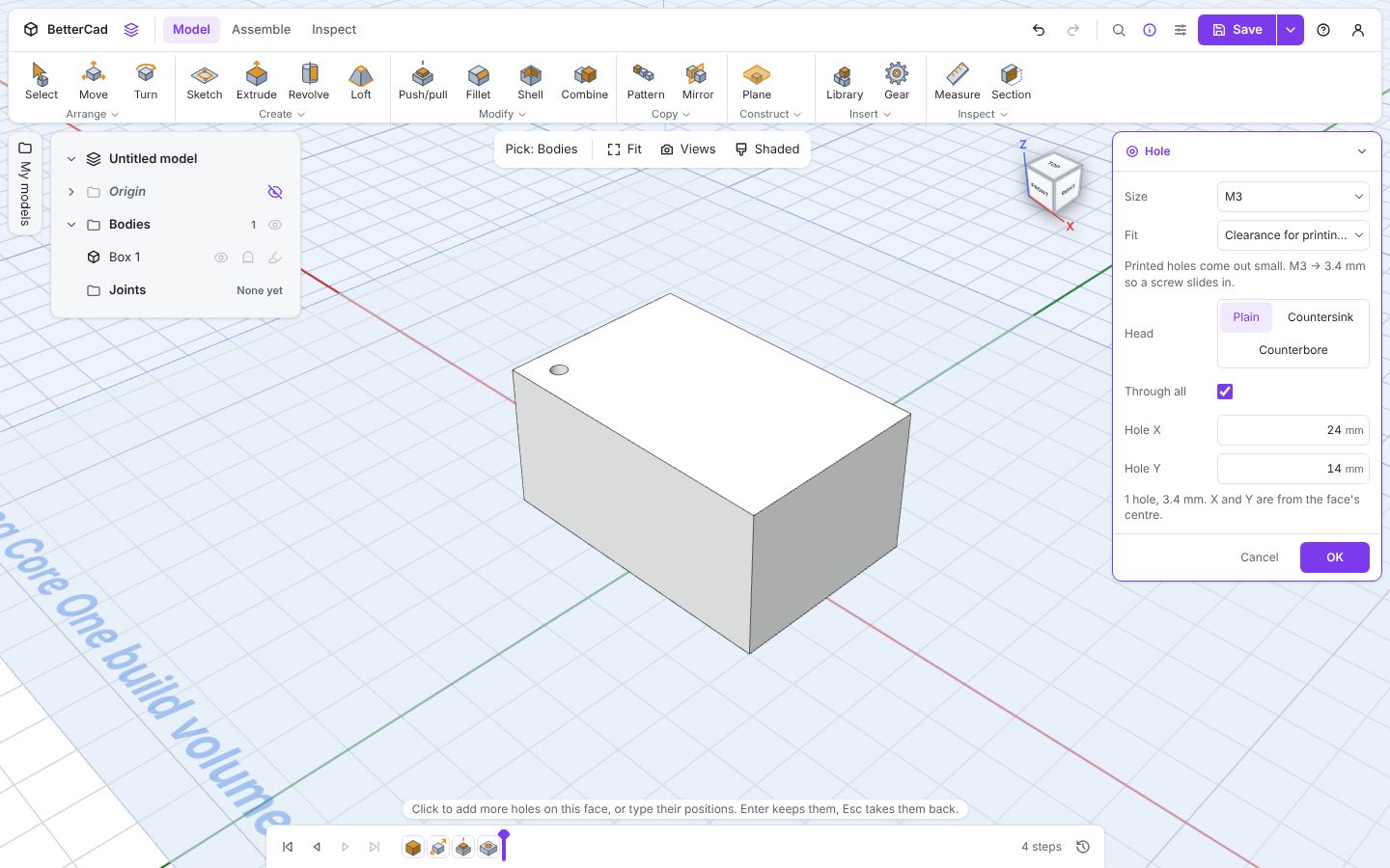
The panel shows Size: M3 and Fit: Clearance for printing, with a note: “Printed holes come out small. M3 → 3.4 mm so a screw slides in.”
- Click near the other three corners.
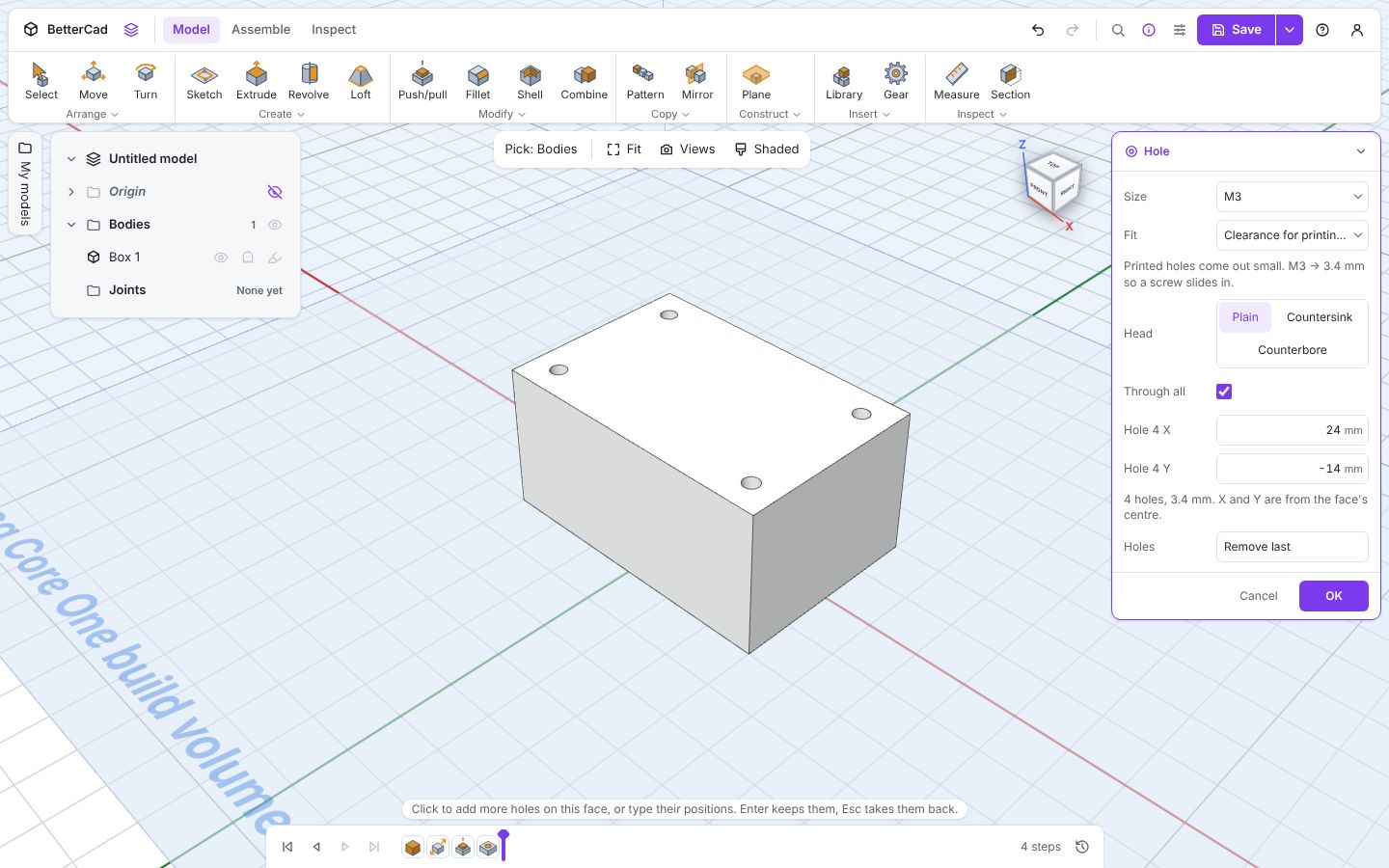
- Clicking by eye is rarely where you want a hole to end up. Each hole has X and Y boxes in the panel, measured from the centre of the face. The panel shows the hole you placed last, and Remove last takes one back. For a tidy pattern, place each hole and type its position before the next:
24and14,-24and14,-24and-14,24and-14. - Leave Through all ticked and press Enter.
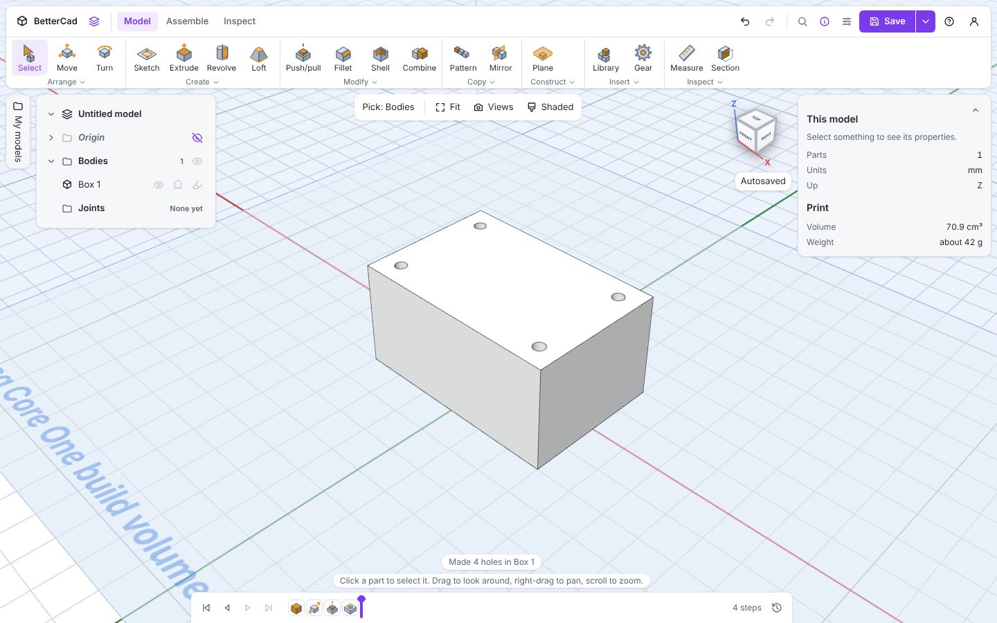
BetterCad reports Made 4 holes in Box 1.
Choosing a fit
Open the Fit menu to see what else the tool can make.
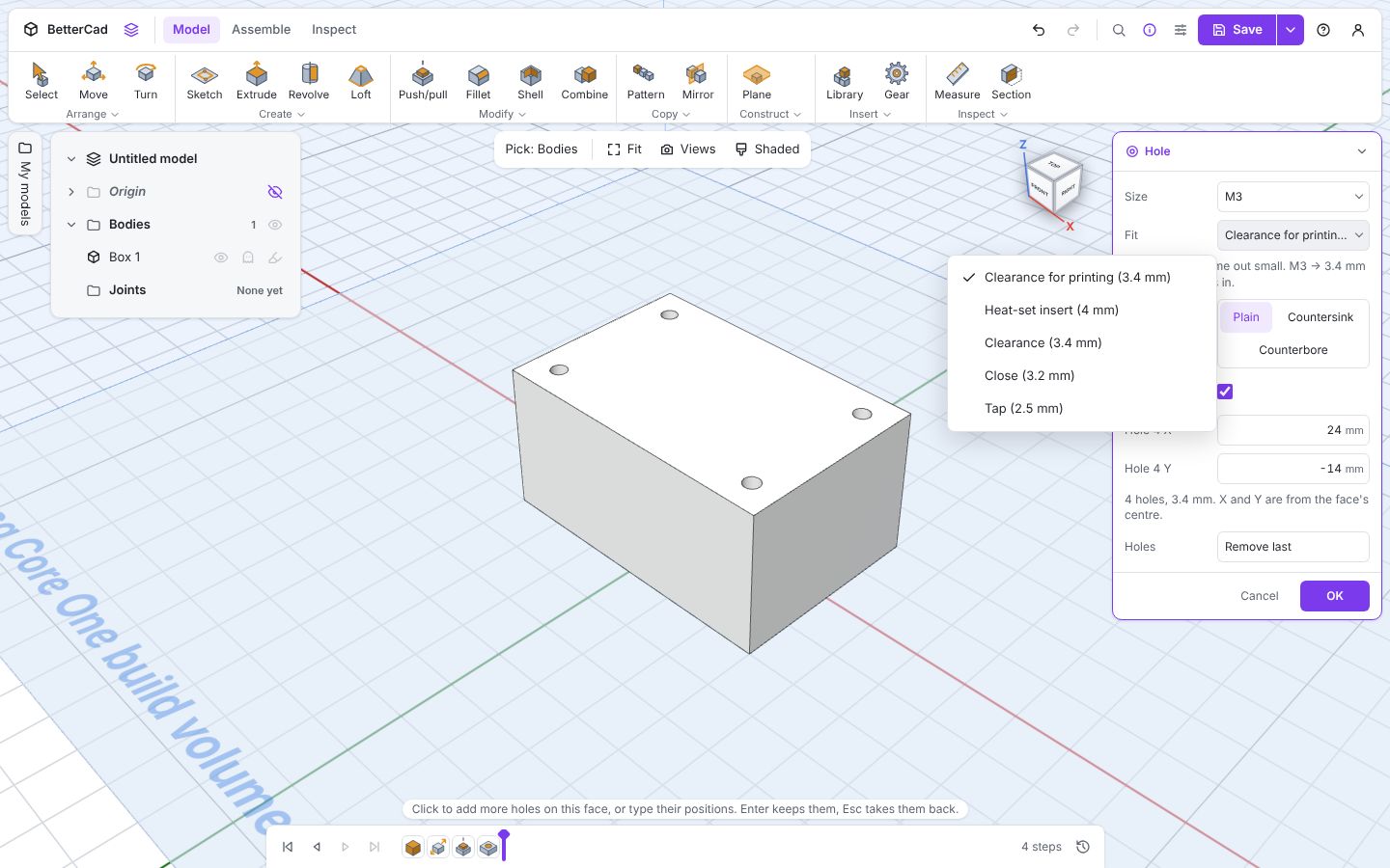
| Fit | For an M3 screw | Use it when |
|---|---|---|
| Clearance for printing | 3.4 mm | The screw slides through a printed hole. Start here |
| Heat-set insert | 4 mm | You’ll melt a brass threaded insert into the hole |
| Clearance | 3.4 mm | The standard clearance size, for parts that won’t be printed |
| Close | 3.2 mm | A snug hole, for lining parts up |
| Tap | 2.5 mm | You’ll cut a thread, or let a screw cut its own |
Head adds a recess so the screw head sits flush: Countersink for cone-headed screws, Counterbore for cap heads.
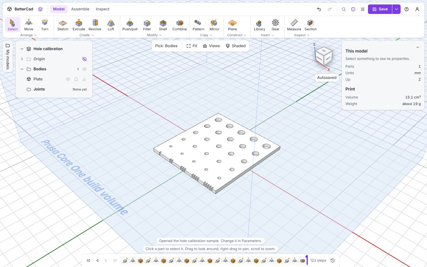
Every printer is a little different. BetterCad includes a Hole calibration sample: a small plate of test holes you print once, then tell BetterCad which one your screw fitted. After that, every printed hole is right for your machine. Print It Right, the next course, walks through it.
Cut with a hole shape
The Hole tool makes round screw holes. For any other opening, use the trick Tinkercad made famous: turn a shape into a hole, then group it with a solid. The enclosure needs an 8 mm opening in one end for a cable.
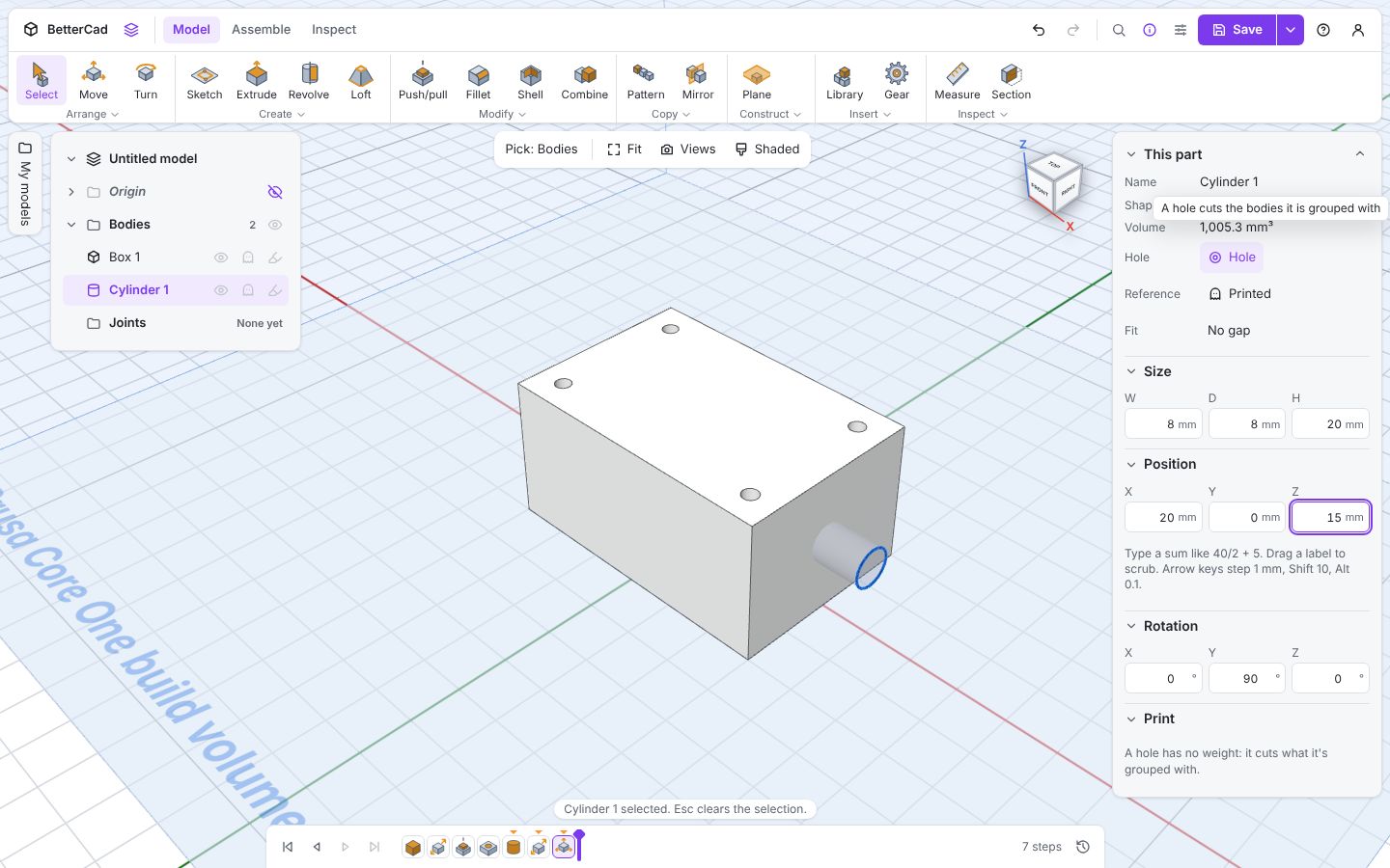
- Open the Library and click Cylinder.
- In Properties, set its size to
8,8and20. - Under Rotation, set Y to
90. The cylinder lies on its side. - Under Position, set X to
20and Z to15. It now pokes out through the end wall. - Click Solid beside Hole in Properties. It changes to Hole, and BetterCad says Cylinder 1 will cut when grouped.
- Click the box, then Shift-click the cylinder so both are selected.
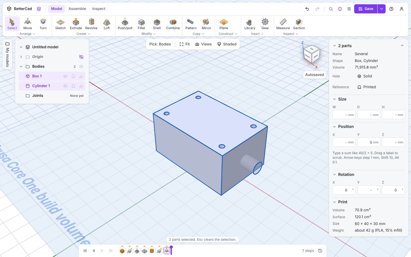
- Press Ctrl+G.
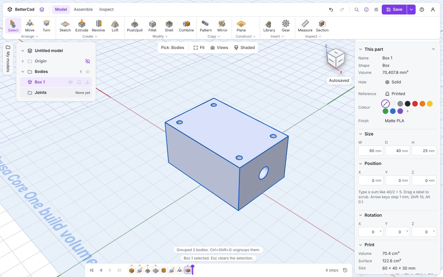
The cylinder is gone and a hole is left where it was. BetterCad reports Grouped 2 bodies. Ctrl+Shift+G ungroups them.
Grouping two solids joins them into one part. Grouping a solid with a hole cuts the hole out. That one idea builds a surprising number of parts.
The Combine tool
Group is the quick way. Combine (C) is the full-control version, with three operations:
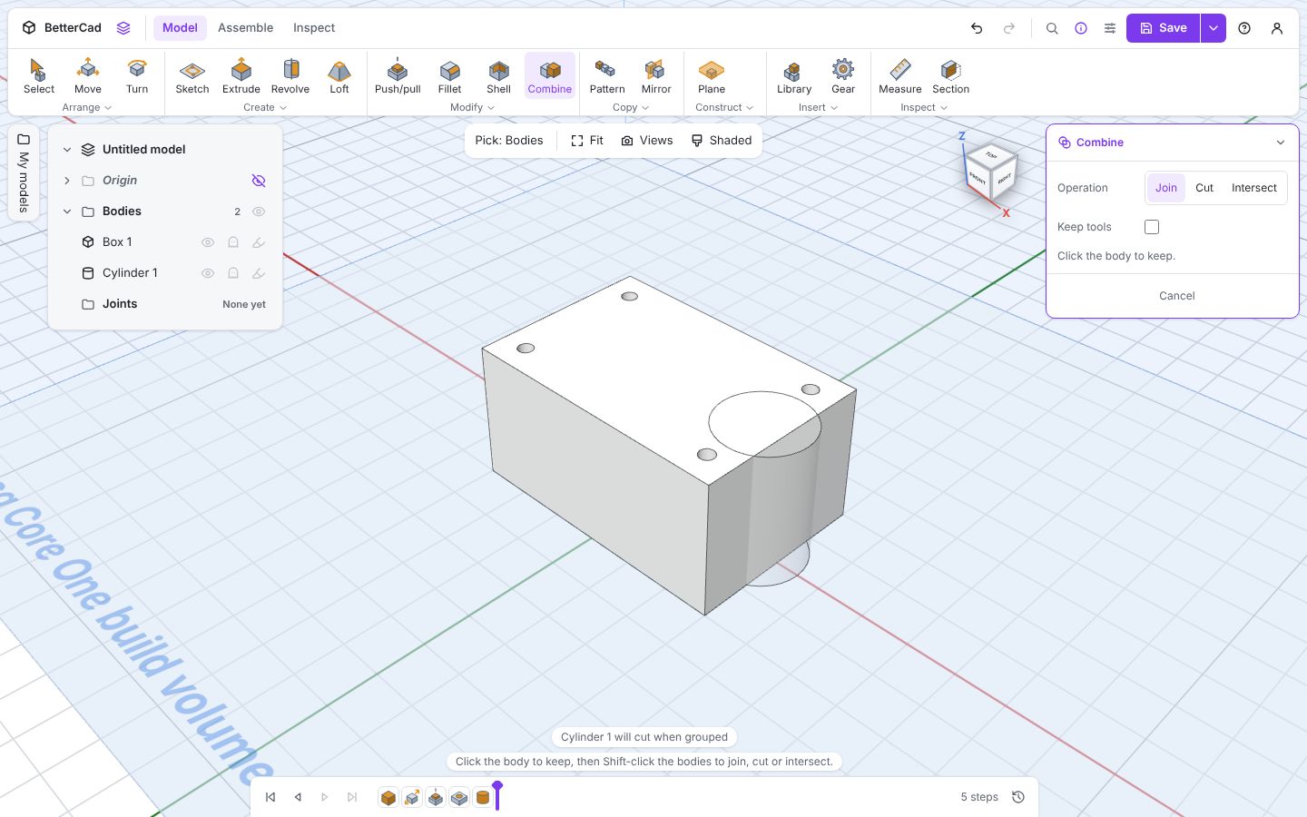
| Operation | Result |
|---|---|
| Join | The parts become one |
| Cut | The second part is removed from the first |
| Intersect | Only the bit where they overlap is kept |
Tick Keep tools if you want the cutting part to stay afterwards, which is handy when one shape needs to cut several parts.
Keep the model open. Next you’ll round it off and hollow it out.
Try it Yourself
- Add a countersunk M3 hole to a spare box and use Section (X) to look inside it.
- Make a rectangular slot: add a Box, make it a hole, push it through a wall and group.
- Add a Sphere that overlaps a Box, then use Combine with Intersect. What’s left?
Common Issues
Problem: I grouped the parts and nothing was cut. Solution: Ungroup with Ctrl+Shift+G, select the cutting shape and switch it from Solid to Hole, then group again. Why: Grouping solids joins them. Only a shape marked Hole cuts.
Problem: The cable hole only goes part of the way through the wall. Solution: Ungroup, make the hole shape longer or move it so it sticks out on both sides of the wall, then group again. Why: A hole shape only removes material where it overlaps the solid.
Problem: My printed holes are still too tight. Solution: Print the Hole calibration sample and set your printer’s hole offset. Why: The 0.4 mm allowance is a good average, but nozzles, materials and slicers all differ.
Check your understanding
Quick quiz 1 of 3
Why does “Clearance for printing” make a 3.4 mm hole for an M3 screw?
Quick quiz 2 of 3
What happens when you group a solid with a shape marked Hole?
Quick quiz 3 of 3
Which Fit would you choose for a brass threaded insert?
You can use the arrows ← → on your keyboard to navigate between lessons.
Comments