Schematic Symbol and Electrical Details
Lay out the schematic symbol for your Snakie part, record its I2C address and tell Snakie its voltage limits so circuits can be checked
By Kevin McAleer, 5 Minutes
Page last updated November 21, 2026

So far you’ve described what the part looks like. Now you’ll describe how it behaves: its circuit symbol, its I2C address and the voltage it’s happy with. This is the information that lets Snakie catch mistakes before they cost you a sensor.
The schematic symbol
Click Schematic in the top bar.
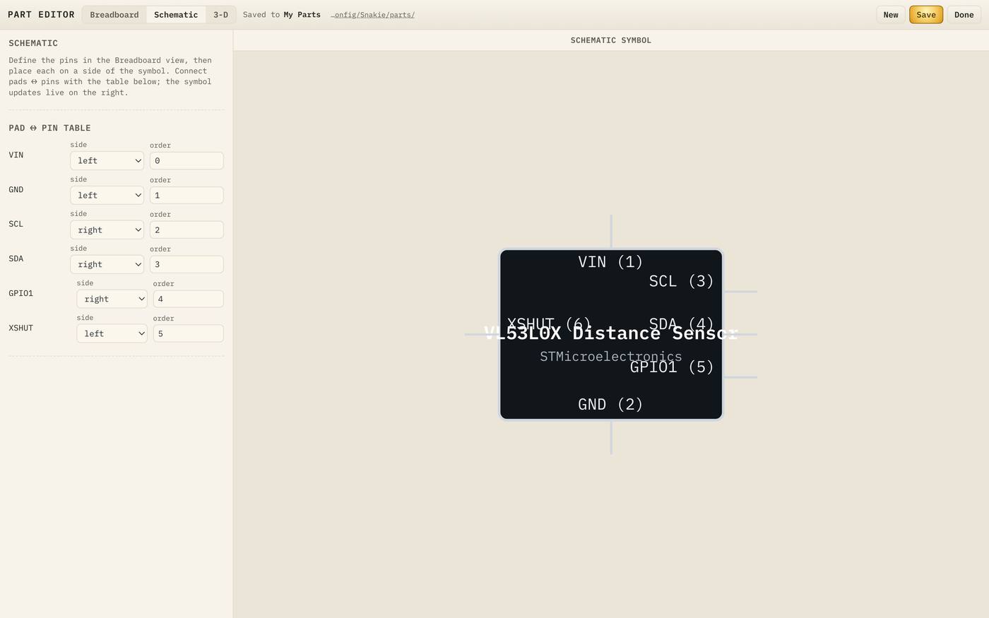
On the right is the symbol: a box with the part’s name, the manufacturer, and a pin on each side. On the left is the Pad ↔ pin table, with one row per pin.
| Column | What it sets |
|---|---|
| side | Which side of the box the pin is on: left, right, top or bottom |
| order | Its position along that side. Lower numbers come first |
There’s a loose convention for symbols that makes circuits easier to read:
- Inputs and control pins on the left
- Outputs and buses on the right
- Power at the top and ground at the bottom
For our sensor, put SCL, SDA and GPIO1 on the right and XSHUT on the left. The symbol updates as you choose.
The symbol doesn’t have to match the physical board. It’s a diagram, laid out for clarity.
Click Breadboard to go back.
The I2C address
Every I2C device answers to an address. The VL53L0X uses 0x29.
- Scroll the side panel to I²C.
- Type
0x29into Add address and click Add.
The address appears as a chip, and Snakie recognises it: next to it you’ll see VL53L0X / VL53L1X ToF.
Why bother? Snakie’s I²C-detect instrument scans the bus on your real board. When it finds something at 0x29, it can now suggest your part by name. A chip with two possible addresses, such as the BME280 at 0x76 or 0x77, gets both.
Electrical behaviour
Scroll to Electrical. The Model box tells Snakie’s circuit checker what kind of thing this is.
| Model | Use it for |
|---|---|
| Passive (no model) | Parts that are only drawn. Wires pass through |
| Source (battery / PSU) | Anything that supplies power |
| Regulator (LDO / buck) | Parts that turn one voltage into another |
| Consumer (load) | Sensors, displays, motors: anything that uses power |
| Resistor, Potentiometer, LED, Diode, Switch / button | The basic components |
A sensor is a Consumer (load). Choose it and more boxes appear.
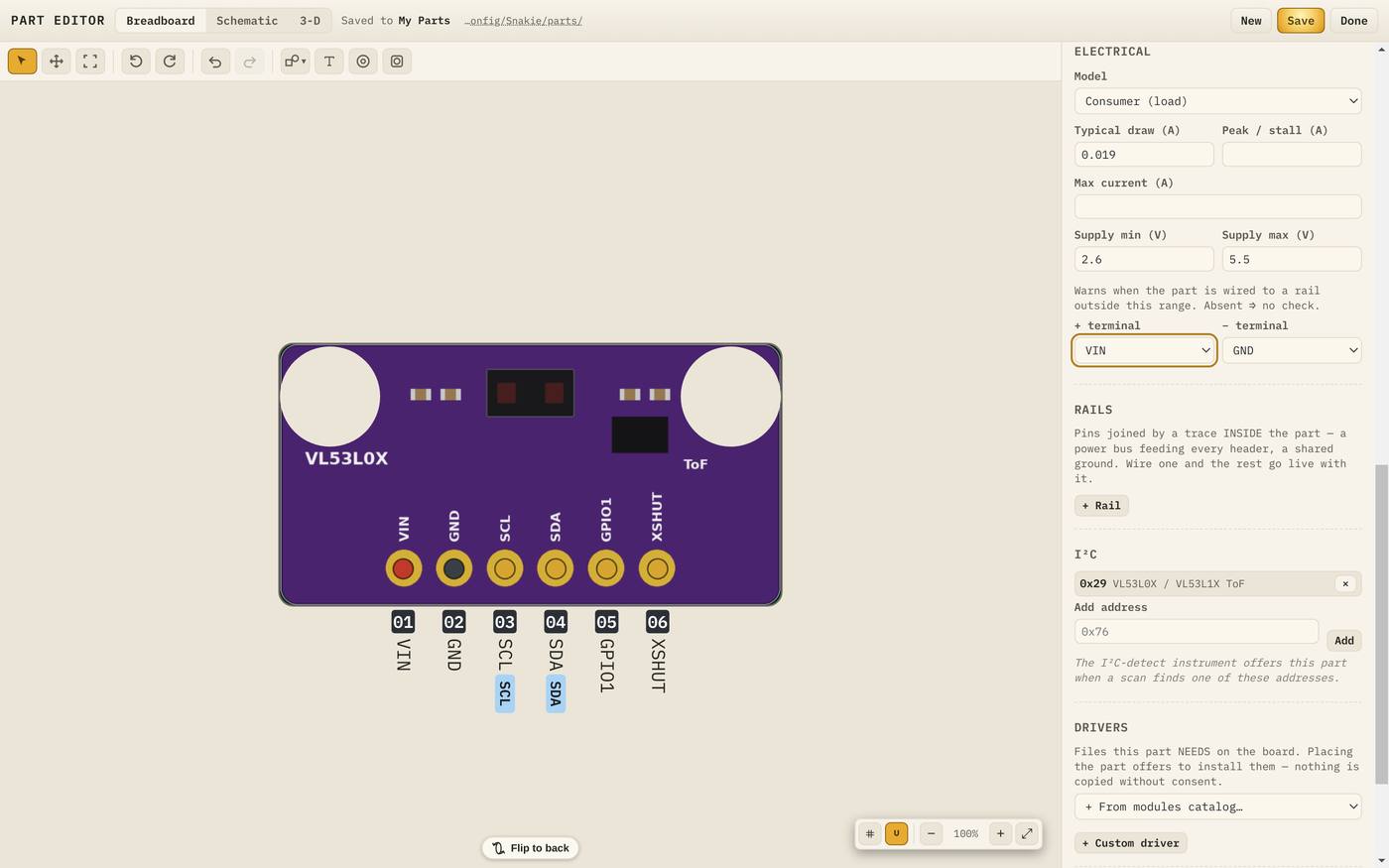
Fill them in from the datasheet:
| Field | Value | Meaning |
|---|---|---|
| Typical draw (A) | 0.019 | About 19 mA while measuring |
| Supply min (V) | 2.6 | The lowest voltage the breakout runs on |
| Supply max (V) | 5.5 | The highest voltage it survives |
| + terminal | VIN | The pin power goes in |
| − terminal | GND | The pin power returns through |
Snakie now warns you when the part is wired to a rail outside 2.6 to 5.5 V. If you leave the supply boxes empty, there’s no check.
Rails
The Rails section is for pins that are joined by a trace inside the part. A motor driver with three GND pins is a good example: wire one and all three are grounded.
Our sensor has one of each pin, so it needs no rails. When you do need one, click + Rail and choose the pins that belong together.
Try it Yourself
- Arrange the schematic symbol as described.
- Add the address
0x29. - Set the model to Consumer and fill in the five values.
- Save.
- Look up a part you own. What are its supply limits and typical current?
Common Issues
Problem: The pin names overlap the part name on the symbol. Solution: Move a pin to another side, or shorten the part’s name. Why: The symbol is a small box, and long names in the middle collide with pins on the sides.
Problem: The Pad ↔ pin table is empty. Solution: Add pins in the Breadboard view first. Why: The schematic only arranges pins that already exist.
Problem: I don’t know my part’s current draw. Solution: Fill in just the supply limits, which are easy to find. Why: The voltage check is the one that protects your hardware.
Check your understanding
Quick quiz 1 of 3
Does the schematic symbol have to match the real board’s layout?
Quick quiz 2 of 3
Why record the part’s I2C address?
Quick quiz 3 of 3
Which electrical model fits a sensor?
You can use the arrows ← → on your keyboard to navigate between lessons.
Comments