Holes That Fit
Calibrate BetterCad's hole offset to your own 3D printer with a test plate, so screw holes come out the right size every time
By Kevin McAleer, 6 Minutes
Page last updated November 20, 2026

Draw a 3 mm hole, print it, and try an M3 screw. It won’t go in. Printed holes come out small: the plastic is squeezed slightly wider than the path the nozzle follows, and a circle is drawn as a string of short straight lines that cut the corners.
Every maker meets this. BetterCad deals with it using one number, the hole offset, and gives you a quick way to find the right value for your printer.
How BetterCad sizes a hole
The Hole tool (H) asks for the screw, not the hole. With Fit set to Clearance for printing, it makes the hole the screw’s size plus the hole offset.
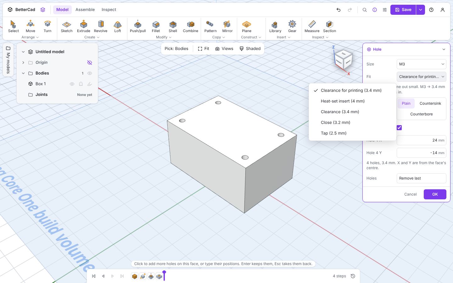
With the default offset of 0.4 mm, an M3 hole is drawn at 3.4 mm, so that it prints at something close to 3.1 or 3.2 and the screw slides in.
| Screw | Drawn at (0.4 mm offset) |
|---|---|
| M2 | 2.4 mm |
| M2.5 | 2.9 mm |
| M3 | 3.4 mm |
| M4 | 4.4 mm |
| M5 | 5.4 mm |
| M6 | 6.4 mm |
The offset is in the Print panel under Holes, and you can set it anywhere from 0 to 1 mm.
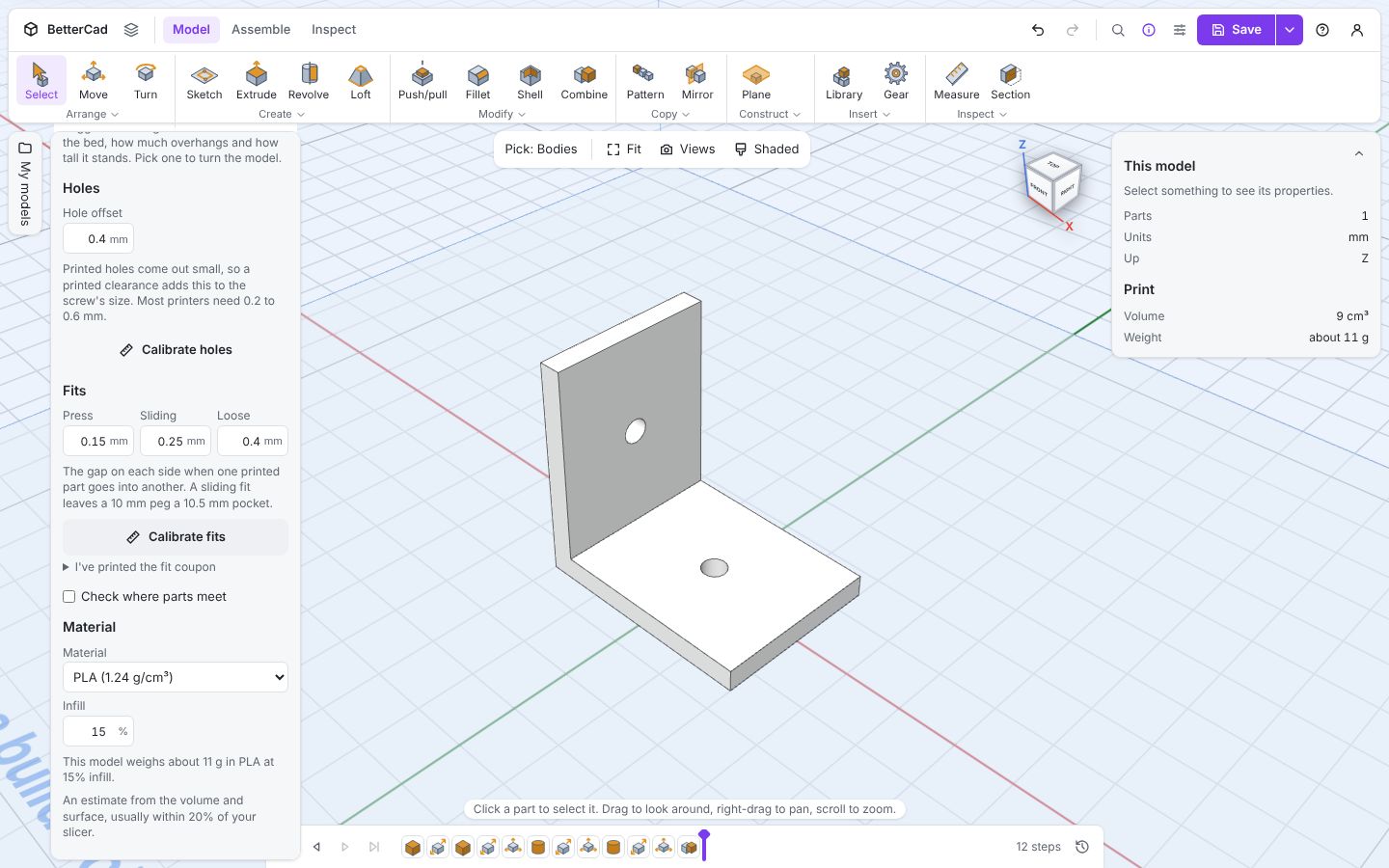
The panel says most printers need 0.2 to 0.6 mm. So which are you?
Print the test plate
- In the Print panel, click Calibrate holes.
BetterCad opens a ready-made test plate as a new model.
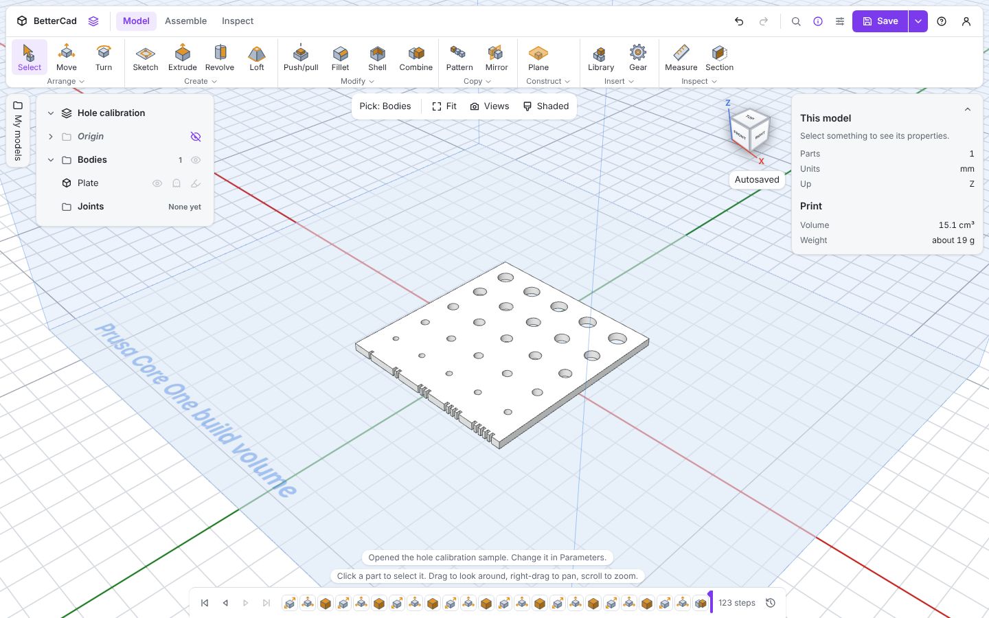
It’s a 3 mm thick plate with a grid of holes:
- Rows, from the front: M2, M2.5, M3, M4, M5, M6
- Columns, from the left: offsets of 0.2, 0.3, 0.4, 0.5 and 0.6 mm
- Notches on the front edge count the column. One notch is 0.2 mm, five is 0.6 mm
- Export it (Ctrl+E) as a 3MF or STL.
- Slice it with your normal settings and print it flat. Use the material and layer height you use most.
It’s small and quick, and it’s the most useful ten grams of plastic you’ll print this year.
Read the result
- Take the screw size you use most. For most robot builders that’s M3.
- Find its row and try the screw in each hole, starting at the one-notch end.
- Stop at the first hole the screw slides through without being forced or screwed in.
- Count the notches below that column. That’s your offset.
| The screw first slides through at | Your offset |
|---|---|
| One notch | 0.2 mm |
| Two notches | 0.3 mm |
| Three notches | 0.4 mm |
| Four notches | 0.5 mm |
| Five notches | 0.6 mm |
Check a second size if you have the screws. They usually agree. If they don’t, go with the size you use most.
Set it
Back in your own model:
- Open the Print panel and type your number into Hole offset.
- If you saved a printer in lesson 1, click Save to it so every future model gets the same value.
From now on, every new Clearance for printing hole uses your offset.
What about holes you’ve already made?
Each Hole step remembers the offset it was made with. Changing the offset doesn’t silently resize anything, because a model that changes shape behind your back is worse than one that’s slightly wrong.
When a model has printed-clearance holes made at a different offset, the Print panel shows a button: Update N holes. Click it and those steps are edited to the new offset in one go, as a single undo step.
Holes the offset doesn’t touch
| Fit | Why it’s left alone |
|---|---|
| Heat-set insert | Insert makers quote the printed hole size directly |
| Clearance, Close | Standard sizes for drilled or machined parts |
| Tap | The drill size for cutting a thread |
Only Clearance for printing uses your offset. And it applies to holes made with the Hole tool. A circle you sketch and cut yourself is exactly the size you drew, so add the allowance yourself.
Try it Yourself
- Print the hole calibration plate and find your offset for M3.
- Set the offset, then make a 20 × 20 × 3 mm plate with one M3 hole. Print it and try the screw.
- Change the offset by 0.1 mm in a model that already has holes. What does the Print panel offer?
Common Issues
Problem: The screw fits a different column on the M3 row than on the M5 row. Solution: Use the value for the size you use most, or split the difference. Why: Small circles are affected more by how the slicer draws curves.
Problem: None of the holes fit, even at five notches. Solution: Check your slicer isn’t shrinking holes or over-extruding. Calibrate flow first, then print the plate again. Why: An offset over 0.6 mm usually points to an extrusion problem, not a design one.
Problem: My holes fitted in PLA but are tight in PETG. Solution: Print the plate again in PETG and save a second printer for it, such as “A1 Mini PETG”. Why: Materials flow and shrink differently.
Check your understanding
Quick quiz 1 of 3
Why do printed holes come out small?
Quick quiz 2 of 3
On the test plate, which hole tells you your offset?
Quick quiz 3 of 3
You change the hole offset. What happens to holes already in the model?
You can use the arrows ← → on your keyboard to navigate between lessons.
Comments