
My First Robot Just Got Five New Senses
SMARS — the screwless, tracked chassis my whole channel is built on — just gained five senses it never had: sight, sound, movement, expression and balance. Five Arduino Modulino modules, about €55 in parts I already owned, no soldering anywhere, and the brain running all of it isn't even made by the same company that made the sensors.
21 August 202616 minute read
By Kevin McAleer
Share this article on
Table of Contents
- SMARS is a test bed, not a comeback
- What changed, and what didn’t
- The brain that doesn’t care who made the sensors
- Old eyes vs new eyes
- Wiring the two supplies
- The code: five senses, one shared trick
- Sense one — See (Modulino Distance)
- Sense two — Hear/speak (Modulino Buzzer)
- Sense three — Move (Modulino Motors)
- Sense four — Show (Modulino LED Matrix)
- Sense five — Measure (Modulino Movement)
- How it gets installed: Snakie, one click at a time
- Parts list
- Gotchas
- Where this actually leaves SMARS
My First Robot Just Got Five New Senses
SMARS — the screwless, tracked chassis my whole channel is built on — just gained five senses it never had: sight, sound, movement, expression and balance. Five Arduino Modulino modules, about €55 in parts I already owned, no soldering anywhere, and the brain running all of it isn't even made by the same company that made the sensors.
Video
For every project I create, I often make a corresponding YouTube video. Sometimes, there might be more than one video for a single project. You can find these videos in this section.
Explore more through this this dedicated video.
Ahoy there makers!
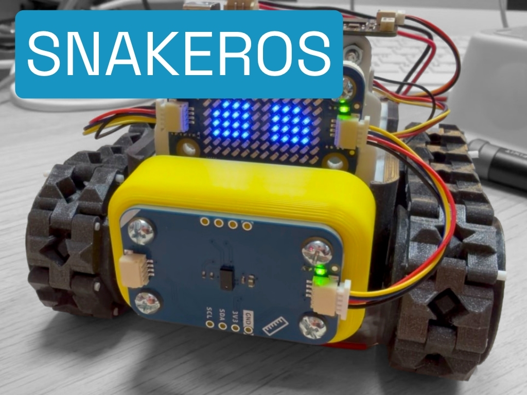
This is SMARS — the screwless, tracked chassis that’s been part of this channel since the very beginning. Six years and six previous rebuilds later, it just did five things it was never built to do: it stopped itself in front of an obstacle, played a tune, drove itself across the bench, flashed an expression on a tiny LED face, and reacted to being tilted by hand. No soldering iron came anywhere near it. About €55 in parts, all of which I already owned. And the board actually running all of it isn’t even made by the same company that made the sensors.
This post is the standalone write-up: the parts, the two 3D-printed pieces that made it possible, the real code behind every sense (including the one extra step a non-Arduino board needs that the video only has time to show once), the wiring for the one connection that genuinely isn’t click-together, and a proper gotchas section. If you want the demo with sound and a face reacting in real time, watch the video — everything you need to build this yourself lives here.
SMARS is a test bed, not a comeback
I want to get one framing right before anything else, because it’s the whole reason this chassis was the obvious choice for this build. SMARS has never been dormant. It’s the platform I keep coming back to every time a genuinely new wave of electronics shows up, and it’s been that way since 2020:
| Build | Date | Link |
|---|---|---|
| SMARS Quad | 1 July 2020 | kevsrobots.com/blog/smars-beginnings |
| SMARS Quad | 16 August 2020 | kevsrobots.com/blog/smars-quad |
| SMARS Inventor (Pimoroni Inventor 2040 W) | 29 August 2022 | kevsrobots.com/blog/smars_inventor |
| SMARS Mini | 22 January 2023 | kevsrobots.com/blog/smars-mini |
| PicoSMARS 2 (Raspberry Pi Pico W) | 5 October 2023 | kevsrobots.com/blog/picosmars |
| SMARS Q (Arduino Uno Q) | 19 October 2025 | kevsrobots.com/projects/smars-q |
| Modulino SMARS | this build | you are here |
Same screwless PLA/ABS chassis every time — the one creator Kevin Thomas designed in 2016 specifically so a kid without access to a 3D printer’s worth of hardware experience could still build a robot, “without screws and without soldering any part.” The electronics are the variable. This is simply the newest instalment, and it’s the first time the hardware and the software have both been genuinely click-together on the same robot at the same time.
What changed, and what didn’t
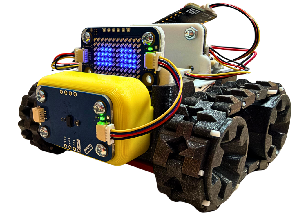
The original SMARS brain was classic hobby-robotics kit: an Arduino Uno R3, a Fundumoto motor shield, and an HC-SR04 ultrasonic rangefinder mounted at the front — Kevin’s own long-standing nickname for it is the robot’s “eyes.” That whole stack is gone. In its place: five Arduino Modulino modules, one per sense, running on an UnexpectedMaker FeatherS2 Neo.
What didn’t change is just as important to the story: the two N20 150RPM micro metal gear motors, the wheels and tracks, and the swappable 9V battery are all exactly stock. Every bit of what actually moves this robot is exactly what it’s always been. The senses are new. The legs are original.
Two new 3D-printed parts make the swap possible:
- A Modulino holder, which replaces the old Uno bay and carries the FeatherS2 Neo plus four of the five Modulinos (everything except Distance).
- A Modulino Distance mount, which replaces the original HC-SR04 holder and sits at the front, in exactly the spot the ultrasonic “eyes” used to occupy.
Both STL files are downloadable — see the parts list below.
The brain that doesn’t care who made the sensors
Here’s the claim this whole build rests on, stated plainly, exactly as it’s said in the video: these are Arduino’s sensors, this is not an Arduino board, and it doesn’t care.
The UnexpectedMaker FeatherS2 Neo is made by Seon Rozenblum, an independent Australian maker — no documented partnership with Arduino at all. It’s an ESP32-S2 board: a single-core 240MHz Xtensa LX7, 4MB flash plus 2MB PSRAM, WiFi but genuinely no Bluetooth (the ESP32-S2 silicon has no Bluetooth radio, full stop). I picked it for two reasons: it has an onboard Qwiic-compatible connector, so the whole Modulino chain plugs straight in with no adapter, and it has its own LiPo battery connector, so the brain’s own power is onboard too.
That’s not a soft “well, they probably speak the same protocol” claim. It’s Arduino’s own documentation, for their own software:
“Any board that has I2C and can run a modern version of MicroPython is supported.”
—
arduino/arduino-modulino-mpy, Arduino’s official MicroPython library — the exact package this build installs
Arduino’s own hardware docs already scope support broadly before you even get to the library: the Modulino Buttons docs page states the modules are “Compatible with the Arduino UNO R4 WiFi or any board with a Qwiic interface.” Independent voices say the same thing even more bluntly — DroneBot Workshop’s Modulino guide states “it doesn’t even have to be an Arduino, and it doesn’t have to have a Qwiic connector,” and that “any microcontroller that has 3.3V I²C” can work with these modules, demonstrating it themselves on a board with no Qwiic port at all by soldering directly to the I2C lines.
The reason this all just works is the connector standard underneath it. Modulino’s connector, SparkFun’s Qwiic, and Adafruit’s STEMMA QT are the same thing, mechanically and electrically: a polarised, 1mm-pitch, 4-pin JST-SH connector running at a fixed 3.3V, with the same pin order every time (GND, 3.3V, SDA, SCL). Adafruit’s own documentation names Modulino directly: “The STEMMA QT connector is identical to the Qwiic connector and uses the same pin ordering,” and Modulino modules “have the same voltage (3.3V) and JST connection as Qwiic so you can treat it the same.” That’s why five modules from Arduino click straight into a board Arduino has never heard of, with zero adapters. (One practical ceiling worth knowing, even though this build is nowhere near it: SparkFun’s own MultiPort guide puts a real-world Qwiic daisy-chain limit at around seven boards before the shared 3.3V pull-ups and the cable’s ~226mA current limit start to bite. Five is comfortable.)
Every Modulino module carries two Qwiic connectors, wired in parallel, so you click one into the next and just keep going — no wiring diagram, no breadboard.
Old eyes vs new eyes
The HC-SR04 got called SMARS’s “eyes” because it genuinely has two of them side by side — one transmitter to send a 40kHz ping, one receiver to listen for the echo. It needed four wires straight into the Uno (VCC, Trig, Echo, GND), and code to time that echo yourself, every single reading.
The Modulino Distance sensor doesn’t ping at all. It’s a VL53L4CD time-of-flight sensor — a laser instead of sound, timing actual light bouncing back rather than an echo. It doesn’t get its own wires either; it just joins the same Qwiic chain as every other sense on the robot, and the sensor chip does its own timing onboard.
Worth being precise here rather than declaring a flat upgrade: the VL53L4CD’s maximum range is around 1.2 metres, against the HC-SR04’s roughly 4 metres. SMARS always had eyes right here — they’re not better at everything, just better for this: a close-range obstacle-stop on a small tracked robot doesn’t need 4 metres of range, and it very much benefits from not needing you to hand-time an echo pulse.
Wiring the two supplies
Here’s the one honest asterisk on “everything clicks together.” Almost every connection on this robot is Qwiic — click, click, click, done — including the brain’s own power, which just plugs into the FeatherS2 Neo’s onboard JST LiPo socket. But Modulino Motors runs its own separate supply, and that one has to be wired in by hand.
Modulino Motors is built around a MAX22211 dual H-bridge driver, delivering up to 3.8A per channel to two brushed DC motors (or one bipolar stepper). Its logic side runs at 3.3V over Qwiic like everything else, but the motor supply itself is a separate domain wanting 5–24V — confirmed word-for-word against Arduino’s own hardware docs, not just an internal parts catalog. The stock SMARS 9V sits comfortably inside that window, so the stock battery feeds the Modulino Motors screw terminals (VIN / GND) directly — no boost converter, no second battery pack needed. It’s the one part of this robot that’s never changed across six years of rebuilds, and it’s also the one wire I actually had to add by hand.
Don’t try to run the motors off the Qwiic 3.3V rail instead — it can’t source the current, and a stalled motor pulling 3.8A through a Qwiic cable is a fire risk, not a brownout.
One more thing worth saying plainly on the soldering question: the FeatherS2 Neo ships from the factory with a full set of male header pins included, but loose and unsoldered — standard practice across Adafruit’s whole Feather form factor, which this board follows. I never touched them. Nothing on this build was soldered.
The code: five senses, one shared trick
Here’s where this write-up goes further than the video has time to. Arduino’s own MicroPython library works out which pins carry I2C by checking os.uname().machine against a table of known Arduino boards — Nano ESP32, Nano RP2040 Connect, Portenta H7, Portenta C33, and a generic ESP32-S3 fallback. The FeatherS2 Neo is an ESP32-S2, not an S3, and it isn’t Arduino’s board at all, so it isn’t in that table. Call ModulinoDistance() with no arguments on this robot and you don’t get a distance reading — you get:
RuntimeError: I2C interface couldn't be determined automatically for '<your board>'
That’s not a wiring fault, and nothing is wrong with the module. Every Modulino class simply accepts an i2c_bus argument, and once you hand it one, the auto-detect problem disappears entirely. This is genuinely the more interesting proof of the cross-vendor claim than the bare “it just works” line — the library doesn’t guess for a board it’s never met, but it also doesn’t refuse to work with one. It just needs telling.
The FeatherS2 Neo’s I2C pins are SCL on GPIO 9 and SDA on GPIO 8, confirmed directly against MicroPython’s own UM_FEATHERS2NEO board configuration (MICROPY_HW_I2C0_SCL / MICROPY_HW_I2C0_SDA). Build the bus once, and every sense on the chain shares it:
from machine import I2C, Pin

i2c = I2C(0, scl=Pin(9), sda=Pin(8))
Sense one — See (Modulino Distance)
from modulino import ModulinoDistance

distance = ModulinoDistance(i2c_bus=i2c)

while True:
    print(distance.distance)     # centimetres, or None when out of range
.distance returns None rather than a number when nothing is in range — worth checking for before comparing, or a stray None will crash the comparison.
Sense two — Hear/speak (Modulino Buzzer)
from modulino import ModulinoBuzzer

buzzer = ModulinoBuzzer(i2c_bus=i2c)

buzzer.tone(440, 500, blocking=True)   # A4 for half a second
buzzer.no_tone()
blocking=True waits for the note to finish before returning; leave it off and your code carries on while the note plays — which matters inside a robot’s control loop, where stopping for half a second means driving blind for half a second.
Sense three — Move (Modulino Motors)
from modulino import ModulinoMotors

motors = ModulinoMotors(i2c_bus=i2c)

motors.speed_a = 60          # 0-100%
motors.speed_b = 60
motors.invert_b = True       # opposite side of a rover drives backwards

print(motors.sensed_current)  # (mA, mA) - a stalled motor shows up here

motors.stop()                 # brake
motors.release()              # coast
sensed_current is a genuinely nice touch — the driver reports per-channel current sensing, so a stalled motor shows up in code rather than as a mystery.
Sense four — Show (Modulino LED Matrix)
from modulino import ModulinoLEDMatrix

matrix = ModulinoLEDMatrix(i2c_bus=i2c, address=0x39)

matrix.set_pixel(3, 4)
matrix.show()          # nothing lights up until you call this
The LED Matrix is worth a specific warning: every drawing call writes to a buffer in the board’s own memory, not to the panel. Nothing lights up until you call .show(). If your matrix stays dark and the code looks right, this is almost always why. On a non-Arduino board, naming the I2C address explicitly (0x39, the module’s re-addressable I2C address) skips the library’s auto-discovery, which — like the distance sensor — doesn’t find every board on its own.
Sense five — Measure (Modulino Movement)
from modulino import ModulinoMovement

movement = ModulinoMovement(i2c_bus=i2c)

while True:
    print(movement.acceleration)      # g, as .x / .y / .z
    print(movement.angular_velocity)  # degrees per second
At rest, .acceleration should read close to 1g on the Z axis (gravity, doing the only work) — a handy sanity check that the board is talking sense before trusting anything else it says. The gyroscope measures rate of turn, not angle, so getting an actual tilt angle out means integrating over time.
That’s genuinely the entire difference between “designed for this board” and “designed for a board it’s never met” — two lines, naming the pins and handing them over as the I2C bus. Everything else about each sense is identical.
How it gets installed: Snakie, one click at a time
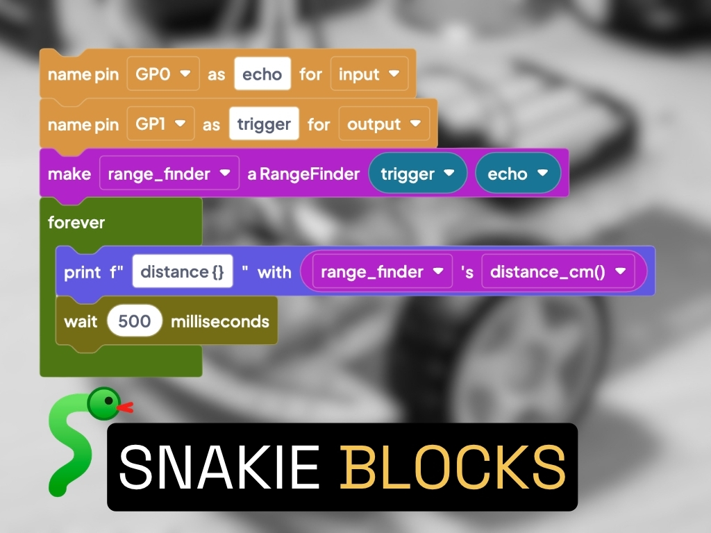
The code above is what’s actually running underneath, but I didn’t hand-write any of the driver plumbing. I used Snakie, the free, open-source MicroPython editor I’ve been building — drag a Modulino part onto the board, and it offers to install the driver library. Say yes to the consent prompt, and it’s done: one package (arduino/arduino-modulino-mpy) covers every Modulino, brought in once no matter how many modules your design uses. That’s a one-click install after a consent prompt, not something silent happening in the background.
Every one of the five senses on this robot got its driver installed exactly the same way. Hardware is modular — click a module onto the chain. Software is modular too — drag a part, approve the install, done. This is the first build where both of those are demonstrably true of the same robot at the same time.
Parts list
The five Modulinos — €55.06 total, VAT included, all already owned:
- Modulino Distance — VL53L4CD time-of-flight sensor, ABX00102 — €13.10 (store)
- Modulino Buzzer — piezo buzzer with onboard STM32C011, ABX00108 — €7.30 (store)
- Modulino Motors — MAX22211 dual H-bridge, ABX00114 — €12.82 (store)
- Modulino LED Matrix — 8×12 charlieplexed, 96 blue LEDs, ABX00152 — €8.54 (store)
- Modulino Movement — LSM6DSOX 6-axis IMU, ABX00101 — €13.30 (store)
The brain (already owned):
- UnexpectedMaker FeatherS2 Neo — ESP32-S2, Qwiic + LiPo connectors, ~$24.50. MicroPython firmware —
UM_FEATHERS2NEO, mainline since ~v1.18.
Stock SMARS platform (unchanged, already owned):
- SMARS screwless, tracked PLA/ABS chassis — design details on kevsrobots.com
- 2× N20 150RPM micro metal gear motors with gearbox
- Wheels + optional 3D-printed TPU tracks
- Swappable 9V battery
The two new custom parts:
- Modulino holder (replaces the Uno bay) — STL file: modulino_holder.stl
- Modulino Distance mount (replaces the HC-SR04 holder) — STL file: distance_holder.stl
Software:
- Snakie — free, open-source MicroPython editor (GitHub)
- Arduino Modulino MicroPython library — installed automatically via Snakie
- Standard Qwiic/STEMMA QT 4-pin cables — one per module, no soldering
- SMARS repo — github.com/kevinmcaleer/smars
Gotchas
The ESP32-S2 auto-detect trap is the big one, and it’ll bite anyone building this on a non-Arduino board. Arduino’s own library only auto-detects its own boards (Nano ESP32, Nano RP2040 Connect, Portenta H7, Portenta C33) plus a generic ESP32-S3 fallback — not the ESP32-S2 this build actually runs. Every single one of the five Modulino help pages in Snakie’s own catalog carries the identical warning, which tells you how common this trip-up is expected to be. The fix is always the same two lines: build a machine.I2C(...) bus naming your board’s real SCL/SDA pins, and pass it as i2c_bus= to whichever Modulino class you’re constructing. Skip that step and you get a RuntimeError, not a working sensor and definitely not a silent auto-detect on hardware Arduino never tested against.
The Modulino Distance sensor is not a straight upgrade over the old HC-SR04 — it trades range for simplicity. Roughly 1.2m maximum range against the HC-SR04’s ~4m. For a small tracked robot doing close-range obstacle detection, that trade is an easy win. If you’re building something that needs to see across a room, it isn’t.
Two power supplies, not one wire. It would be tidier to say this whole robot runs off one battery, but it doesn’t: the FeatherS2 Neo’s own logic and Qwiic chain run from its onboard LiPo, plugged into its own JST socket, and the Modulino Motors supply rail runs separately off the stock 9V. They share a common ground, but the positive rails stay isolated. Don’t try to feed the motors from the Qwiic 3.3V line — it isn’t rated for it.
A couple of I2C addresses are worth knowing before you scan the bus and get confused. Modulino Buzzer answers at 0x3C, the exact same default address as the extremely common SSD1306/SH1106 OLED family — if you’re adding a status display to a project like this, one of the two has to move. Modulino Motors answers at 0x48, shared with the equally common ADS1115/ADS1015 ADC and TMP102 temperature sensor. Both Buzzer and Motors carry an onboard MCU, so both addresses are software re-addressable if you hit a collision; the four bare-sensor Modulinos (Distance, Thermo, Light, Movement) have no onboard MCU, so their addresses are fixed in silicon and can’t share a chain with a second one of the same module.
The board ships with loose header pins you don’t actually need. The FeatherS2 Neo comes with a full set of male headers in the box, unsoldered, for anyone who wants to hand-solder it into a breadboard or perfboard project. This build never touched them — the Qwiic connectors did all the work.
Where this actually leaves SMARS
The one thing worth taking from all of this: a robot doesn’t need a new chassis to feel brand new. It needs senses that click into place, and a brain that doesn’t care who made them. SMARS has had a new brain every year or two for six years now — this is just the newest one.
So — what should it get next? Tell me in the comments; the best idea might be the next version. And if you want to see it happen, the full build is on YouTube, with the whole demo running start to finish.
I hope you enjoyed this one, and I shall see you next time. Bye for now.
This page is awesome - Show some love!


Comments