KevsRobots Learning Platform
Wall Drawing Robot Tutorial
36% Percent Complete
Introduction
Build the Robot
Programming
Summary
Wiring the Components
Guide to wiring the stepper motors, servo, and Raspberry Pi.
By Kevin McAleer, 1 Minute
Page last updated August 02, 2024
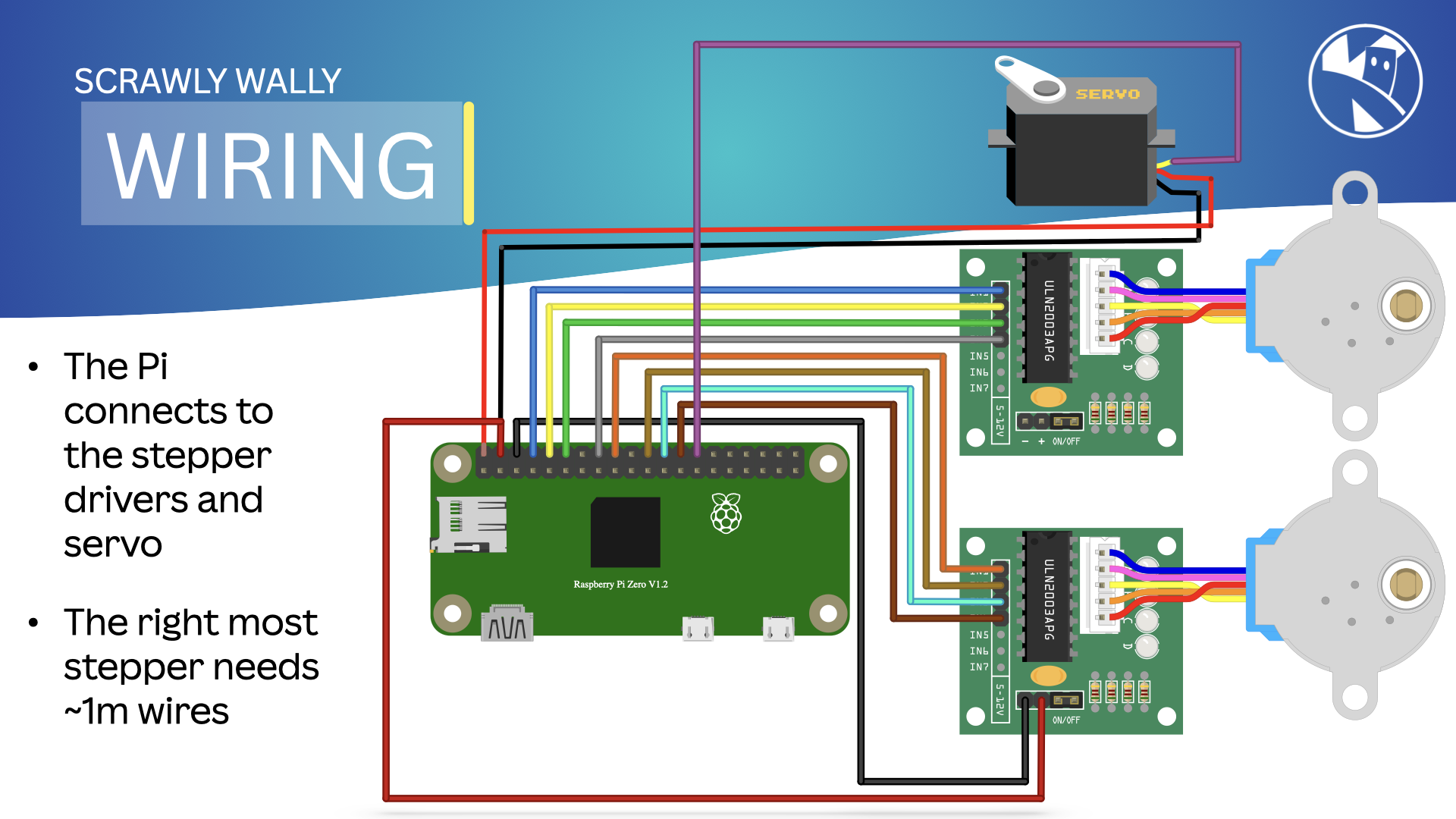
Wiring
Follow these steps to wire the components:
| Item | Action |
|---|---|
Connect the Stepper Motors: Connect the 28BYJ-48 stepper motors to the ULN2003 driver boards. Connect the IN1, IN2, IN3, and IN4 pins on the driver boards to GPIO pins on the Raspberry Pi.Connect the Servo Motor: Connect the servo motor to a PWM-capable GPIO pin on the Raspberry Pi. Connect the power and ground wires of the servo to the Raspberry Pi. Power the Raspberry Pi: Ensure your Raspberry Pi has a stable power supply. |
|
Pin Connections
Here are the pin connections for the components:
| Component | Raspberry Pi Pin |
|---|---|
| Left Stepper, IN1 | GPIO 14 |
| Left Stepper, IN2 | GPIO 15 |
| Left Stepper, IN3 | GPIO 18 |
| Left Stepper, IN4 | GPIO 23 |
| Right Stepper, IN1 | GPIO 24 |
| Right Stepper, IN2 | GPIO 25 |
| Right Stepper, IN3 | GPIO 08 |
| Right Stepper, IN4 | GPIO 07 |
| Servo Signal | GPIO 01 |
With the wiring done, we can now proceed to setting up the Raspberry Pi.
You can use the arrows ← → on your keyboard to navigate between lessons.
Comments