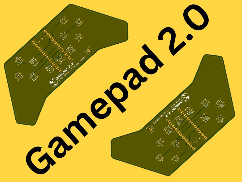
Gamepad 2
Build a Raspberry Pi Pico 2 powered bluetooth remote control for your robot

Videos
For every project I create, I often make a corresponding YouTube video. Sometimes, there might be more than one video for a single project. You can find these videos in this section.
Explore more through these this dedicated videos.
Version 2.0
The Gamepad 2 is a Raspberry Pi Pico 2 powered bluetooth remote control for your robot.
It’s a fun project that combines hardware and software to create a digital remote control that you can interact with.
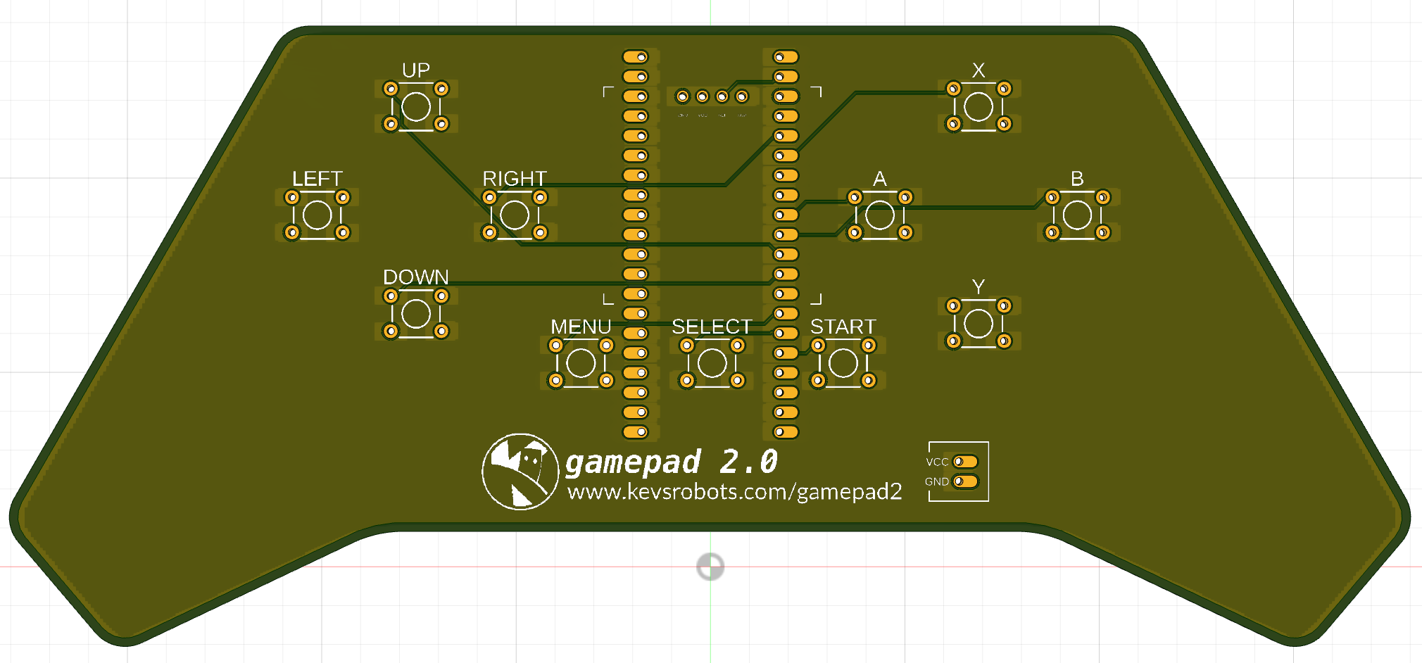
New Features in Version 2.0
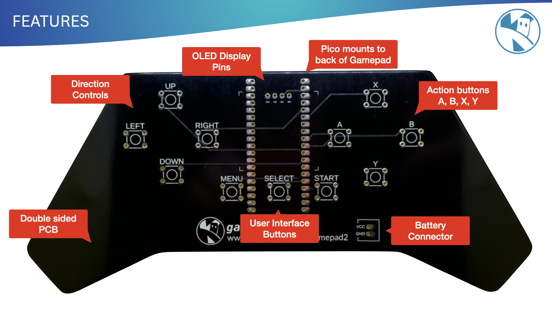
- OLED Display
- Select, Start and Menu buttons for use with the display
- Through holes fixed for Pico
- Button wiring fixed
- Power connector for battery
- MicroPython library

Bill of Materials
To build the Gamepad 2 you will need the following components:
| Item | Description | Quantity | Cost | Total |
|---|---|---|---|---|
| Pico | Raspberry Pi Pico WH or Pico 2 WH | 1 | £4.80 | £4.80 |
| Buttons | 6x6x5mm Tactile Switches | 11 | £0.10 | £1.10 |
| OLED | 0.96” OLED Display 128x64 pixel | 1 | £2.00 | £2.00 |
| Battery | 3.7V LiPo Battery 500mAh | 1 | £5.00 | £5.00 |
| JST Connector | 2 Pin JST Connector | 1 | £0.10 | £0.10 |
| GamePad PCB | Custom PCB | 1 | £6.00 | £6.00 |
| £18.00 |
Assembly
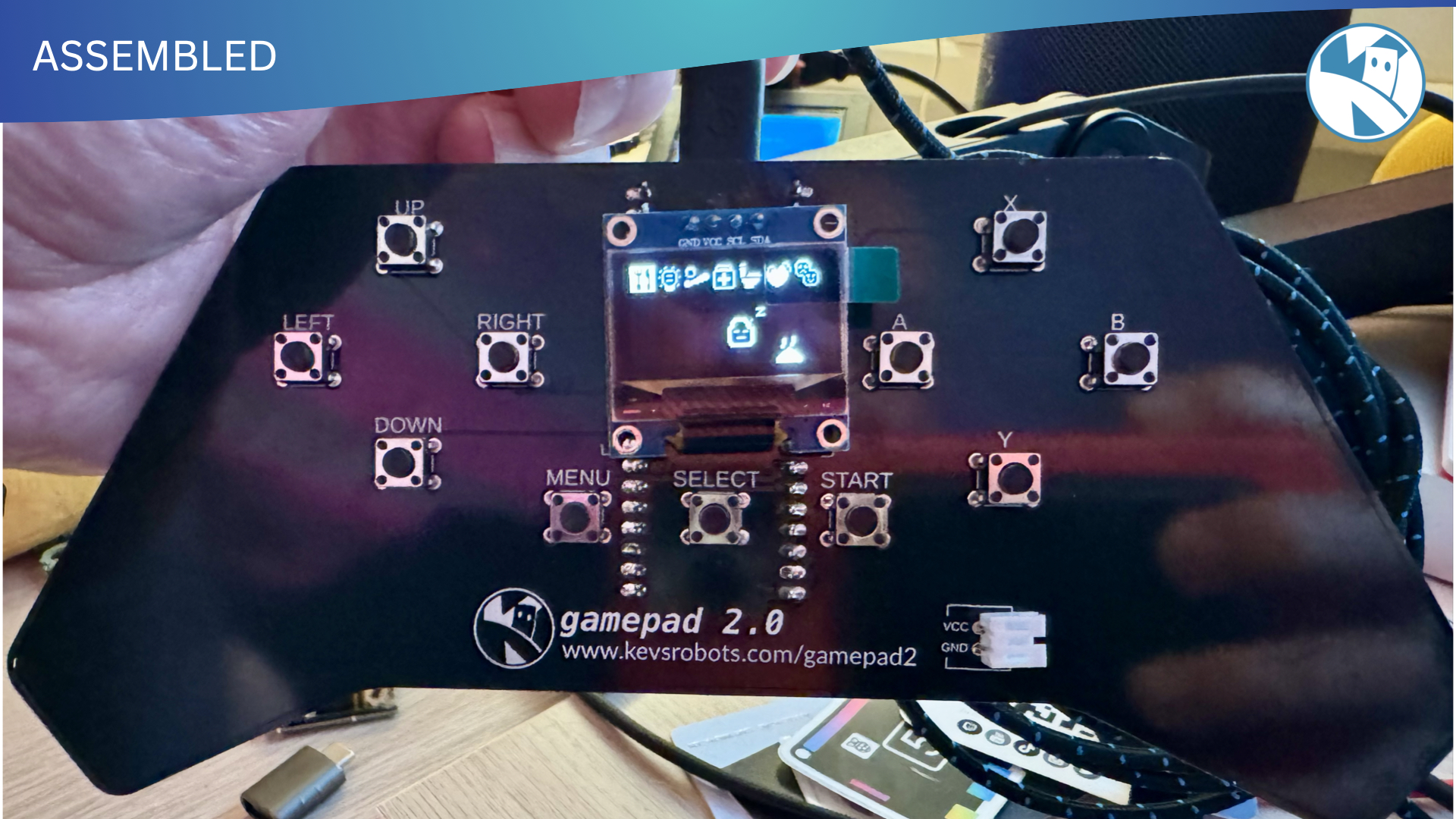
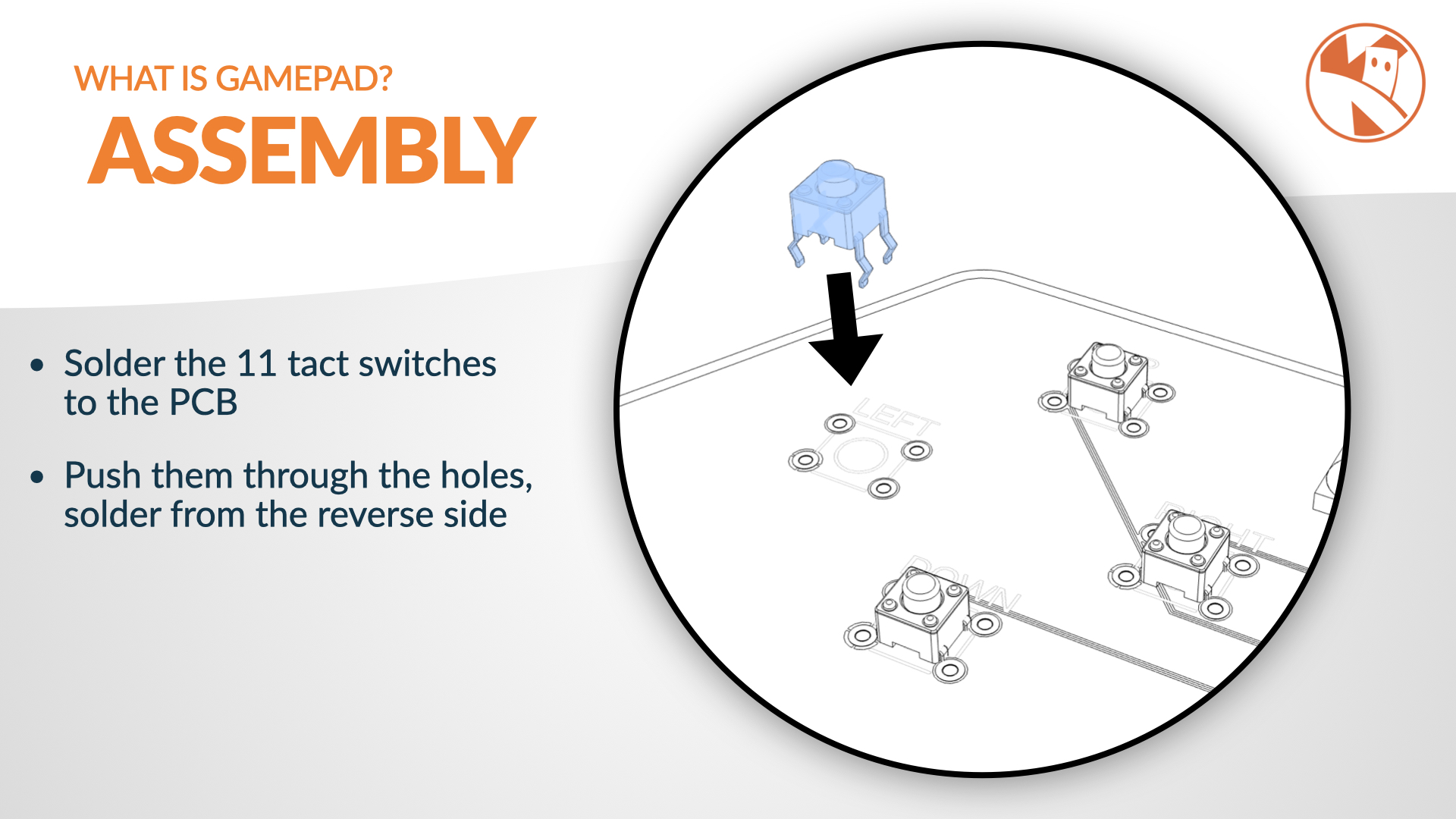
Push the 11 tact switches into the PCB and solder them in place. The switches are all the same so it doesn’t matter which way around they go.
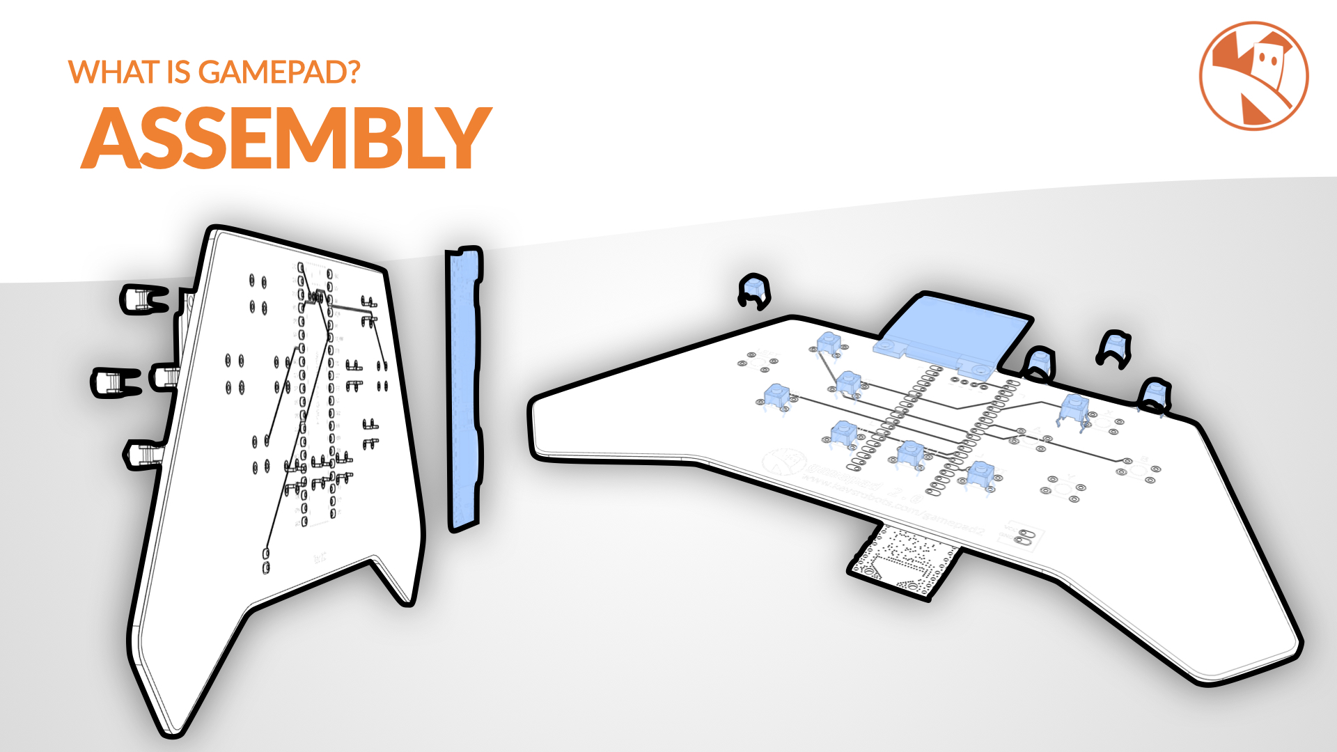
The Pico is mounted on the back of the PCB, and should be soldered from the front.
Notice the little rectanngle on the pcb silkscreen - this indocates the orientation of the Pico, with the micro usb at the top.
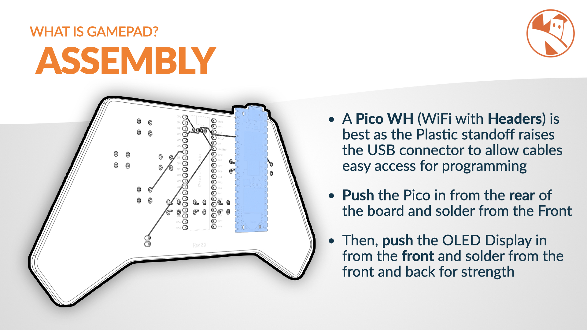
A Pico WH or Pico 2 WH is recommended as the little plastic header pin holder lifts the pico off the pcb slightly, allowing room for the USB connector to be easily connected.
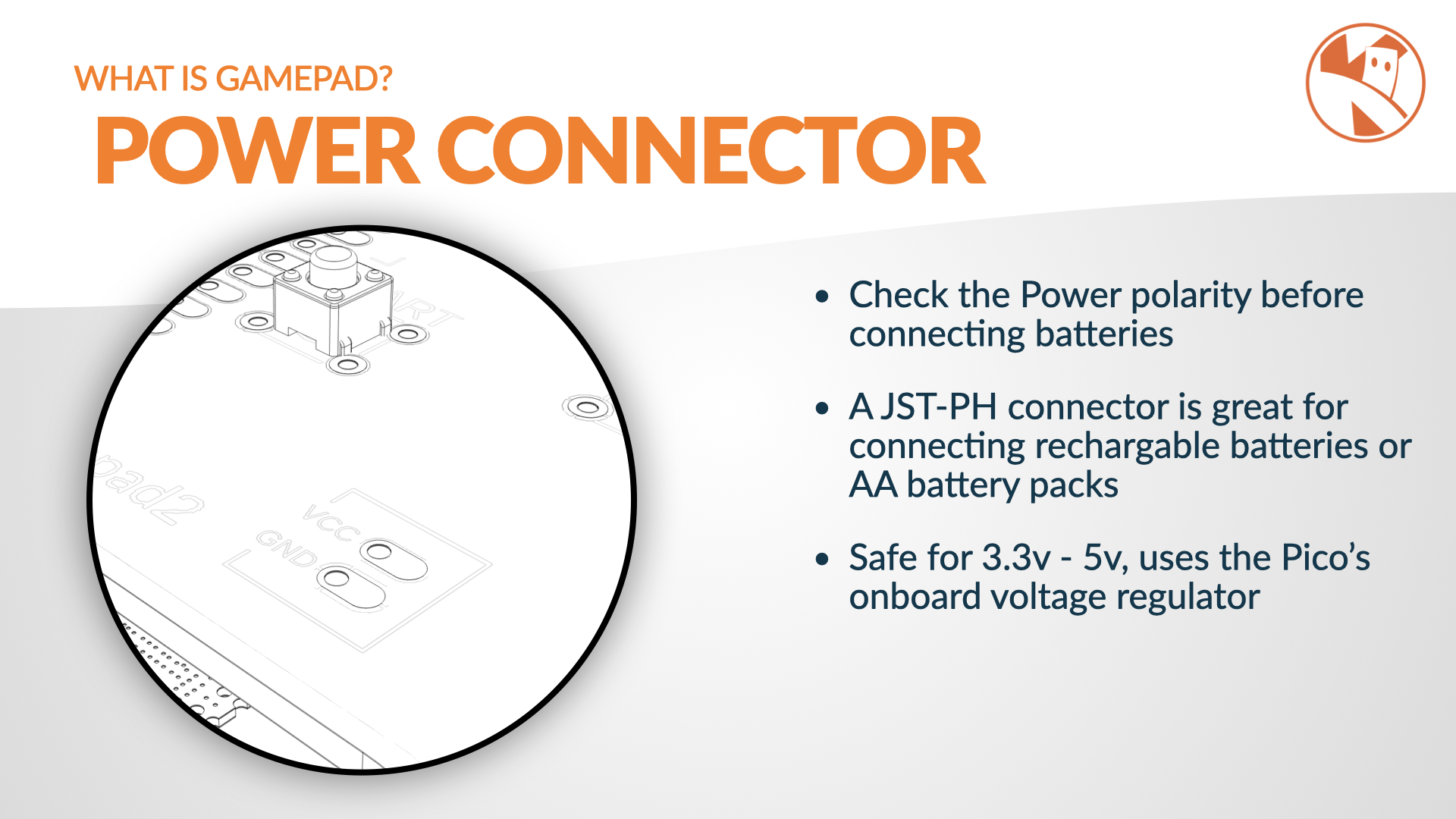
Be sure to check the orientation of the power connector, taking note of the + and - symbols on the PCB.
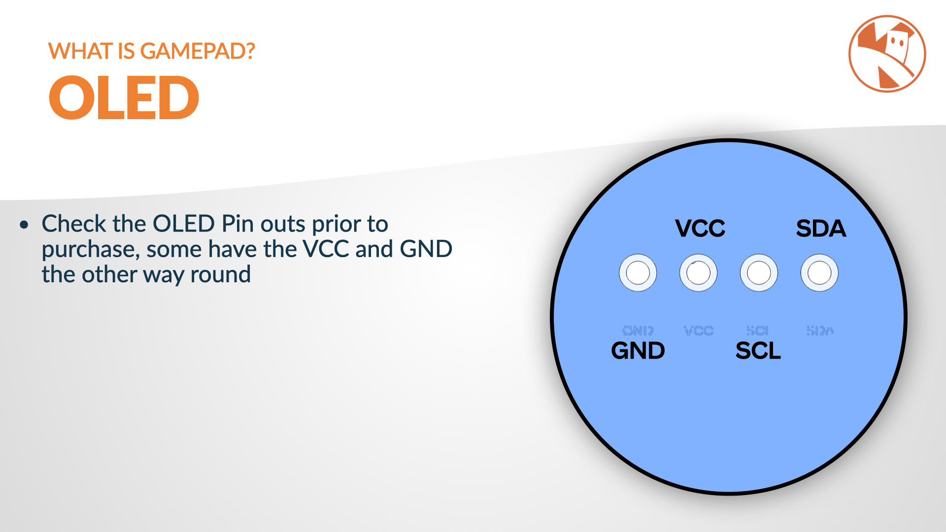
When purchasing the SSD1306 OLED display, be sure to get the 4 pin version - and check that the pins match those on the PCB - GND, VCC, SCL, SDA in that order, some come with the vcc and gnd pins reversed.
Pinouts
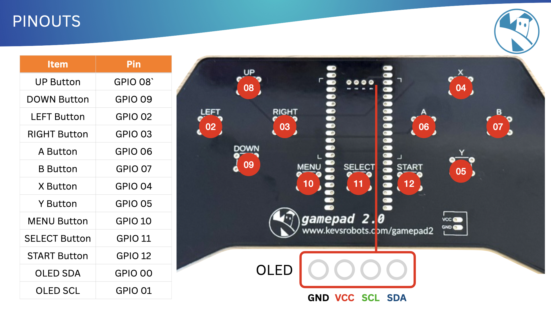
Here are the pinouts for the Pico, OLED and Buttons:
| Item | Pin |
|---|---|
| UP Button | GPIO 08 |
| DOWN Button | GPIO 09 |
| LEFT Button | GPIO 02 |
| RIGHT Button | GPIO 03 |
| A Button | GPIO 06 |
| B Button | GPIO 07 |
| X Button | GPIO 04 |
| Y Button | GPIO 05 |
| MENU Button | GPIO 10 |
| SELECT Button | GPIO 11 |
| START Button | GPIO 12 |
| OLED SDA | GPIO 00 |
| OLED SCL | GPIO 01 |
Software Library
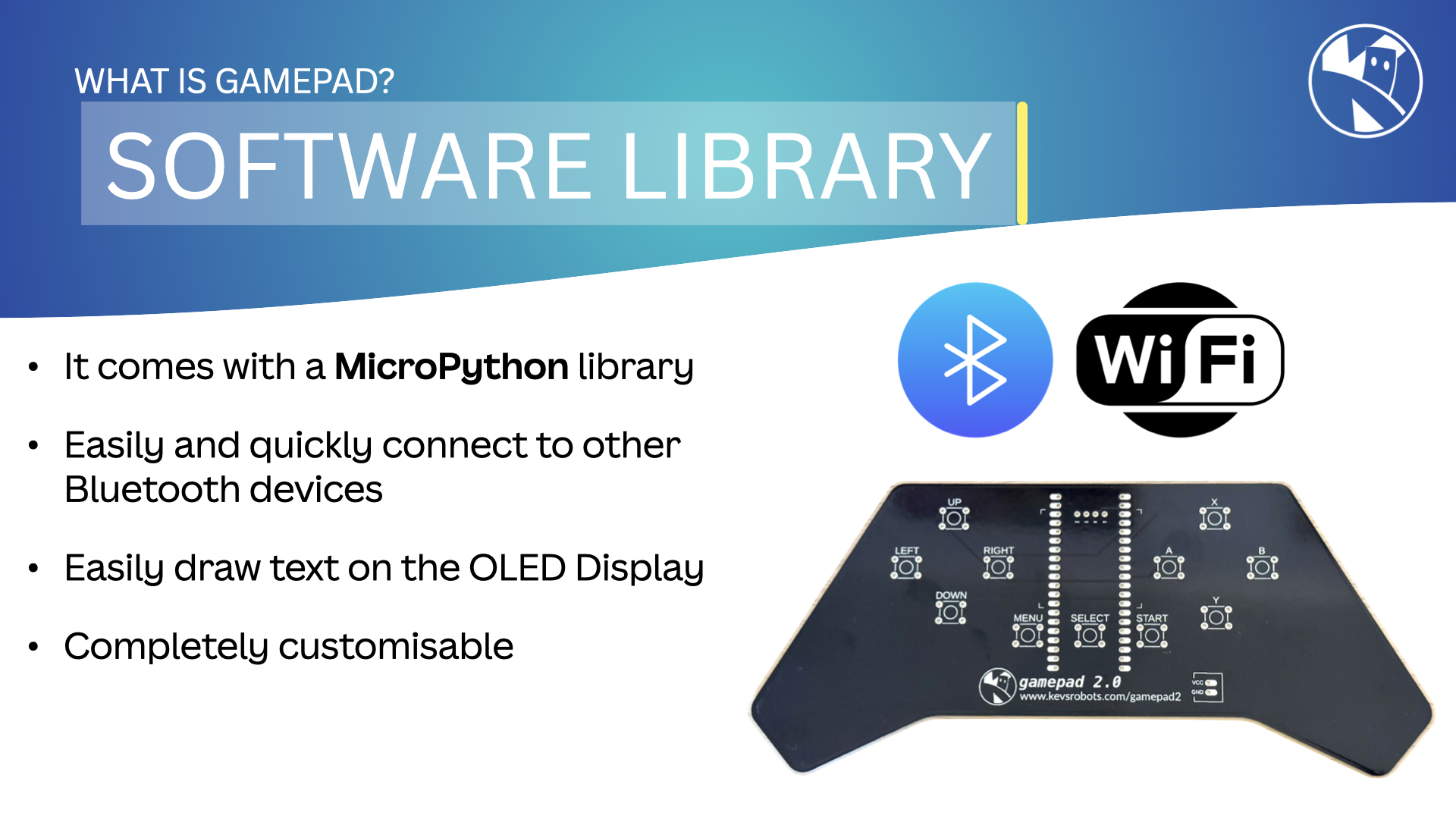
The software for the Gamepad 2 is written in MicroPython and is available on GitHub - https://www.github.com/kevinmcaleer/gamepad
There are 3 classes within the library:
GamePad- the main class that initialises the Pico and the OLED displayButtons- a class that reads the button pressesSSD1306- a class that controls the OLED display, included as a separete fileMotor- a class that controls the motors on the robotGamePadServer- a class that runs a bluetooth server on the Pico for use on the robot that connects to the GamePad
To setup your Gamepad, copy the gamepad.py file to your pico as well as the ssd1306.py file.
There is an example program named test_butttons.py that demonstrates how to use the GamePad library - you can even copy this as main.py to your Pico and it will run when the Pico is powered up.
GamePadServer
To use the gamepad to control a robot you will need to copy the gamepad.py file to your robot. The GamePadServer class will run on the robot and connect to the GamePad. It can check for buttons presses and then respond to them using your own code.
I’ve included a test_gamepad file as an example that works on a burgerbot robot.
This page is awesome - Show some love!


Comments